2-p0265-0282-cm3_en 5 / 19
10秒後にBOOKのページに移動します
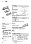
Boss-cut Mounting 傖 Boss-cut/Basic (BZ) 傖 Boss-cut/Rod flange (FZ) 傖 Boss-cut/Rod trunnion (UZ) Boss for the head cover bracket is eliminated and the total length of cylinder is shortened. (mm) o20 .13 o25 .13 o32 .13 o40 .16 Bore size (mm) Foot Flange Single clevis Double clevis (with pin) Trunnion (with nut) Mounting bracket Contents 20 25 32 40 (for minimum order quantity) 2 1 1 1 1 CM-L020B CM-F020B CM-C020B CM-D020B CM3-T020B CM-L032B CM-F032B CM-C032B CM-D032B CM3-T032B CM-L040B CM-F040B CM-C040B CM-D040B CM3-T040B 2 foots, 1 mounting nut 1 flange 1 single clevis, 3 liners Min. order qty. . Order 2 foots per cylinder. .. 3 liners are included with a clevis bracket for adjusting the mounting angle. . . . A clevis pin and retaining rings (split pins for o40) are included. Mounting Brackets/Part No. Specifications Standard Strokes Type Action Fluid Proof pressure Maximum operating pressure Minimum operating pressure Ambient and fluid temperature Lubrication Stroke length tolerance Piston speed Cushion Allowable kinetic energy Pneumatic Double acting, Single rod Air 1.0 MPa 0.7 MPa 0.05 MPa Not required (Non-lube) 50 to 750 mm/s Rubber bumper 20 25 32 40 0.2 J 0.11 J 0.29 J 0.18 J 0.46 J 0.29 J 0.84 J 0.52 J Without auto switch: .10 to +70°C (No freezing) With auto switch: .10 to +60°C (No freezing) +1.4 0 mm Male rod end Female rod end Bore size (mm) Bore size (mm) 20 25 32 40 Standard stroke (mm) Note) 25, 50, 75, 100, 125, 150, 200, 250, 300 . Other intermediate strokes can be manufactured upon receipt of order. Manufacture of intermediate strokes in 1 mm intervals is possible. (Spacers are not used.) . Operate the cylinder within the allowable kinetic energy. Refer to page 270 for details. . Auto switch proper mounting position (detection at stroke end) and its mounting height . Minimum stroke for auto switch mounting . Operating range . Auto switch mounting brackets/Part no. Refer to pages 279 to 282 for cylinders with auto switches. 1 double clevis, 3 liners, 1 clevis pin, 2 retaining rings 1 trunnion, 1 trunnion nut Warning 1. Operate the cylinder within the specified cylinder speed, kinetic energy and lateral load at the rod end. 2. The allowable kinetic energy is different between the cylinders with male rod end and with female rod end due to the different thread sizes. Refer to page 270. 3. When female rod end is used, use a washer, etc. to prevent the contact part at the rod end from being deformed depending on the material of the work piece. Caution 1. Use a thin wrench when tightening the piston rod. Symbol Double acting, Single rod/Rubber bumper Comparison of the Full Length Dimension (Versus CM3尰-尰 type) Series CM3 . . . . .. .. 268