2-p0369-0382-cg3_en 6 / 15
10秒後にBOOKのページに移動します
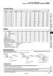
Theoretical Output Weights Mounting Procedure (kg) Bore size (mm) Basic Long male rod end (G) Female rod end (F) Foot Flange Clevis Pivoting bracket Single knuckle joint Double knuckle joint (with pin) Additional weight per 50 mm of stroke Additional weight for switch magnet 20 0.09 0.10 0.08 0.11 0.08 0.05 0.08 0.05 0.05 0.05 0.01 25 0.14 0.15 0.12 0.13 0.10 0.08 0.09 0.09 0.09 0.07 0.01 32 0.20 0.21 0.19 0.16 0.14 0.15 0.17 0.09 0.09 0.09 0.01 40 0.32 0.34 0.29 0.22 0.20 0.23 0.25 0.10 0.13 0.13 0.01 50 0.66 0.70 0.60 0.48 0.34 0.40 0.44 0.22 0.26 0.19 0.01 63 0.92 0.97 0.85 0.72 0.50 0.68 0.80 0.22 0.26 0.23 0.02 80 1.75 1.84 1.61 0.96 0.71 0.71 0.98 0.39 0.64 0.31 0.02 100 2.74 2.85 2.53 1.75 1.35 1.28 1.75 0.57 1.31 0.43 0.04 Basic weight Additional weight for bracket Unit: N Bore size D (mm) Rod size d (mm) Piston area (mm2) Operating direction Operating pressure (MPa) 20 25 32 40 50 63 80 100 8 10 12 14 18 18 22 26 OUT IN OUT IN OUT IN OUT IN OUT IN OUT IN OUT IN OUT IN 314 264 491 412 804 691 1257 1103 1964 1709 3117 2863 5027 4646 7854 7323 0.2 62.8 52.8 98.2 82.4 160.8 138.2 251.4 220.6 392.8 341.8 623.4 572.6 1005.4 929.2 1570.8 1464.6 0.3 94.2 79.2 147.3 123.6 241.2 207.3 377.1 330.9 589.2 512.7 935.1 858.9 1508.1 1393.8 2356.2 2196.9 0.4 125.6 105.6 196.4 164.8 321.6 276.4 502.8 441.2 785.6 683.6 1246.8 1145.2 2010.8 1858.4 3141.6 2929.2 0.5 157 132 245.5 206 402 345.5 628.5 551.5 982 854.5 1558.5 1431.5 2513.5 2323 3927 3661.5 0.6 188.4 158.4 294.6 247.2 482.4 414.6 754.2 661.8 1178.4 1025.4 1870.2 1717.8 3016.2 2787.6 4712.4 4393.8 0.7 219.8 184.8 343.7 288.4 562.8 483.7 879.9 772.1 1374.8 1196.3 2181.9 2004.1 3518.9 3252.2 5497.8 5126.1 Calculation: (Example) CDG3FN20-100 (Built-in magnet, Flange type, o20, 100 mm stroke) . Basic weight ・・・・・・・・・・・・・・・・・・・・・・・・・・・・・・・・・・・・・・・・ 0.09 (Basic type, o20) . Additional weight for bracket ・・・・・・・・・・・・・・・ 0.08 (Flange) . Additional weight for stroke ・・・・・・・・・・・・・・・・・ 0.05/50 mm . Air cylinder stroke ・・・・・・・・・・・・・・・・・・・・・・・・・・・・・・・・ 100 mm . Additional weight for switch magnet ・・・・ 0.01 0.09 + 0.08 + 0.05 x (100/50) + 0.01 = 0.28 kg Series CG3 Air Cylinder Short Type Standard: Double Acting, Single Rod Mounting procedure for rod end nut o20 to o63 o80, o100 Caution 1. Tighten clevis bracket mounting bolts with the following proper tightening torque. o20: 1.5 N・m, o25 to o32: 2.9 N・m, o40: 4.9 N・m o50: 11.8 N・m, o63 to o80: 24.5 N・m, o100: 42.2 N・m 2. For the flange type and the foot type, mount the rod end nut so that distance t (clearance) will be 1 mm or more in order to prevent interference of the nut with the bracket when the rod is retracted. 3. The rod end nut (for male thread) should be mounted so that the hexagon part is on the rod end side. Apply the wrench to the hexagon part. t (Clearance) Flange Foot t (Clearance) Rod end nut (For male thread) Mounting procedure for clevis Follow the procedures below when mounting a pivoting bracket on the clevis type. Clevis pin (Apply grease.) Retaining ring Retaining ring Pivoting bracket Cylinder body Retaining ring Clevis pin (Apply grease.) Retaining ring Cylinder body Pivoting bracket 373 CJ1 CJP CJ2 -Z CJ2 CM2 -Z CM2 CM3 CG1 -Z CG1 CG3 MB -Z MB MB1 CA2 -Z CA2 CS1 CS2 D- -X Technical data