2-p0369-0382-cg3_en 7 / 15
10秒後にBOOKのページに移動します
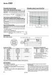
Cylinder stroke (mm) Allowable lateral load at rod end (N) 10 1000 10 100 1 50 100 150 200 250 300 o r !0t !2q y e !1i u w o20 o25 o32 o40 o50 o63 o80 o100 Table (3) Additional Mass Additional mass per 50 mm of stroke Switch magnet Bore size (mm) [g] Table (2) Mass of Cylinder Movable Parts: At Each Rod End/Without Built-in Magnet/0 Stroke Basic Long male rod end (G) Female rod end (F) Bore size (mm) [g] . Mass of the rod end nut is included for the basic type and the long male rod end type (G). 30 36 23 20 54 64 40 25 74 89 62 32 121 146 91 40 254 300 184 50 297 343 226 63 603 683 462 80 935 1047 728 100 20 4 20 31 4 25 44 9 32 61 13 40 99 14 50 99 22 63 148 24 80 207 35 100 Male rod end Female rod end 0.2 0.11 Bore size (mm) 20 0.29 0.18 25 0.46 0.29 32 0.84 0.52 40 1.4 0.91 50 2.38 1.54 63 4.13 2.71 80 6.93 4.54 100 Table (1) Max. Allowable Kinetic Energy [J] Allowable Kinetic Energy Kinetic energy E (J) = (m1 + m2) V2 2 m1 : Mass of cylinder movable parts kg m2 : Load mass kg V : Piston speed at the end m/s Allowable Lateral Load at Rod End . Do not apply a lateral load over the allowable range to the rod end when it is mounted horizontally. Calculation: (Example) CDG3BN40-150 . Standard mass of movable parts: Table (2) Rod end [Basic], Bore size [40] ・・・・・ 121 g . Additional mass: Additional mass of stroke 61 x 150/50 = 183 g ・・・・・・・・・・・・・・・・・・・・ 183 g Switch magnet ・・・・・・・・・・・・・・・・・・・・・・・・・・・・・・・・・・・・・・・・・・・・・・・・・・・・・・・・・・・・・・・・・・・・・・・・・・・ 13 g Total 317 g Bore size (mm) Kit no. CG3N20-PS CG3N25-PS CG3N32-PS CG3N40-PS 20 25 32 40 Contents Replacement Parts/Seal Kit Note) Refer to the following for disassembly/ replacement. Order with a part number for each type and bore size. . The seal kit includes a grease pack (10 g). Order with the following part number when only the grease pack is needed. Grease pack part no.: GR-S-010 (10 g) Note) In the case of cylinders with auto switches, magnets are installed in the piston. . The material for o20 and o25 cylinders with auto switches is made of stainless steel. No. Note Component Parts Description Rod cover Tube cover Piston Piston rod Bushing Bumper A Bumper B Wear ring Rod end nut Rod seal Piston seal Tube gasket 1 2 3 4 5 6 7 8 9 10 11 12 Material Aluminum alloy Aluminum alloy Aluminum alloy Carbon steel. Bearing alloy Resin Resin Resin Carbon steel NBR NBR NBR Hard anodized Hard anodized Chromated Hard chrome plated. Nickel plated With rubber bumper Caution 1. Do not replace the bushings. The bushings are press-fit. To replace them, they must be replaced together with the cover assembly. 2. To replace a seal, apply grease to the new seal before installing it. If the cylinder is put into operation without applying grease to the seal, it could cause the seal to wear significantly, leading to premature air leakage. 3. Cylinders with o50 or larger bore sizes cannot be disassembled. When disassembling cylinders with bore sizes o20 through o40, grip the double flat part of either the head cover or the rod cover with a vise and loosen the other side with a wrench or a monkey wrench, etc., and then remove the cover. When re-tightening, tighten approximately 2 degrees more than the original position. (Cylinders with o50 or larger bore sizes are tightened with a large tightening torque and cannot be disassembled. If disassembly is required, please contact SMC.) Construction Set of the nos. !0, !1, !2 Series CG3 374