2-p0369-0382-cg3_enü@ü@ü@8 / 15
10ĢbīŃé╔BOOKé╠āyü[āWé╔ł┌ō«éĄé▄éĘ
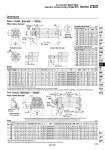
NA F oI F GA GB oD H A AL H1 C C H H AL A oI GA GB MM X Y W Y X W M H2 Z H LX LZ LH B C C H1 AL A oD 8 x J Corner of the cover (o20 to o63) 2 x P MM Width across flats KA Width across flats B1 R0.5 S + Stroke ZZ + Stroke 0 oE .0.05 0 oE .0.05 MM Depth A1 ZZ + Stroke ZZ + Stroke Width across flats B1 Width across flats NA 2 x P 2 x oLC (Knock pin position) S+ Stroke LS+ Stroke ZZ+ Stroke (LT) 4 x oLD 8 x J 15üŗ Width across flats KA Rod part Long male rod end . Use a thin wrench when tightening the piston rod. . Refer to the dimensions of the basic type for the female rod end type and the long male rod end type. (mm) 20 25 32 40 50 63 80 100 Bore size (mm) Symbol Foot A AL D 8 10 12 14 18 18 22 26 GB 6 7 7.5 7.5 12 12 16 16 H2 4 4 4 5.5 8 8 9.5 9.5 LX 32 36 44 54 66 82 100 120 LZ 44 49 58 71 86 106 125 150 M 3 3.5 3.5 4 5 5 5 7 MM M8 x 1.25 M10 x 1.25 M10 x 1.25 M14 x 1.5 M18 x 1.5 M18 x 1.5 M22 x 1.5 M26 x 1.5 B1 C H H1 W 13 17 17 19 27 27 32 41 14 16.5 20 26 32 38 50 60 5 6 6 8 11 11 13 16 12 12.5 11 10.5 15 15 17 20 GA 26 31 38 47 58 72 89 110 B I 34 38.5 45 54.5 70.5 82.5 101 121 KA Width across flats 6 length 3.5 Width across flats 8 length 3.5 Width across flats 10 length 3.5 Width across flats 12 length 3.5 Width across flats 16 length 4.5 Width across flats 16 length 4.5 Width across flats 19 length 4.5 Width across flats 22 length 4.5 LC LD 6 6 7 7 10 12 11 14 LH LS 20 22 25 30 40 45 55 65 33 36 36 35 49 49 56 57 LT (3) (3) (3) (3) (4.5) (4.5) (4.5) (6) NA 24 29 35.5 44 55 69 80 100 P M5 x 0.8 M5 x 0.8 Rc1/8 Rc1/8 Rc1/4 Rc1/4 Rc1/4 Rc3/8 S 57 60 62 62 84 84 104 105 10 10 10 10 17.5 17.5 20 20 X 15 15 16 16.5 22 22 28.5 30 Y 7 7 8 8.5 11 13 14 16 Z 32 35 36 42.5 52.5 52.5 68 68 ZZ 83 89.5 91.5 98 128.5 128.5 157.5 162 4 4 4 4 5 5 6 6 M4 x 0.7 M5 x 0.8 M5 x 0.8 M6 x 1 M8 x 1.25 M10 x 1.5 M10 x 1.5 M12 x 1.75 J 14.5 17.5 17.5 23.5 29 29 35.5 35.5 12 15 15 20.5 26 26 32.5 32.5 20 23 23 29 35 35 44 44 .1 The rod end nut should be mounted in the position t (clearance) so that it will have a clearance of 1 mm or more in order to prevent interference of the nut with the bolt for mounting bracket when the rod is retracted. Sectional view of the rod part (mm) Up to 200 Up to 300 Up to 300 Up to 300 Up to 300 Up to 300 Up to 300 Up to 300 20 25 32 40 50 63 80 100 Bore size (mm) Basic Standard stroke (mm) Up to 200 Up to 300 Up to 300 Up to 300 Up to 300 Up to 300 Up to 300 Up to 300 20 25 32 40 50 63 80 100 Bore size (mm) Long Male Rod End .2 Standard stroke A 18 22 22 30 35 35 40 40 AL 15.5 19.5 19.5 27 32 32 37 37 H 35 40 40 50 58 58 71 71 ZZ 94 102 104 114 144 144 178 179 (mm) Up to 200 Up to 300 Up to 300 Up to 300 Up to 300 Up to 300 Up to 300 Up to 300 20 25 32 40 50 63 80 100 Bore size (mm) Female Rod End Standard stroke A1 8 8 12 13 18 18 21 25 13 14 14 15 16 16 19 22 MM M4 x 0.7 M5 x 0.8 M6 x 1 M8 x 1.25 M10 x 1.5 M10 x 1.5 M14 x 1.5 M16 x 1.5 H 72 76 78 79 102 102 126 130 ZZ A 14.5 17.5 17.5 23.5 29 29 35.5 35.5 AL 12 15 15 20.5 26 26 32.5 32.5 D 8 10 12 14 18 18 22 26 E 12 14 18 25 30 32 40 50 F 2 2 2 2 2 2 3 3 B1 13 17 17 19 27 27 32 41 C 14 16.5 20 26 32 38 50 60 12 12.5 11 10.5 15 15 17 20 GA GB 6 7 7.5 7.5 12 12 16 16 I 26 31 38 47 58 72 89 110 MM M8 x 1.25 M10 x 1.25 M10 x 1.25 M14 x 1.5 M18 x 1.5 M18 x 1.5 M22 x 1.5 M26 x 1.5 NA 24 29 35.5 44 55 69 80 100 P M5 x 0.8 M5 x 0.8 Rc1/8 Rc1/8 Rc1/4 Rc1/4 Rc1/4 Rc3/8 S 57 60 62 62 84 84 104 105 H H1 ZZ 5 6 6 8 11 11 13 16 20 23 23 29 35 35 44 44 79 85 87 93 121 121 151 152 KA M4 x 0.7 depth 7 M5 x 0.8 depth 7.5 M5 x 0.8 depth 8 M6 x 1 depth 10 M8 x 1.25 depth 16 M10 x 1.5 depth 16 M10 x 1.5 depth 22 M12 x 1.75 depth 22 J Width across flats 6 length 3.5 Width across flats 8 length 3.5 Width across flats 10 length 3.5 Width across flats 12 length 3.5 Width across flats 16 length 4.5 Width across flats 16 length 4.5 Width across flats 19 length 4.5 Width across flats 22 length 4.5 .1 Use a thin wrench when tightening the piston rod. .2 Long male rod end type (G) is the same rod end dimensions (A, AL, H) as the CG1 series. .3 When female thread is used, use a washer, etc. to prevent the contact part at the rod end from being deformed depending on the material of the work piece. Dimensions Basic: CG3BN With rubber bumper Bore size Stroke Female rod end With rubber bumper Foot: CG3LN Bore size Stroke Series CG3 Air Cylinder Short Type Standard: Double Acting, Single Rod t (Clearance).1 375 CJ1 CJP CJ2 -Z CJ2 CM2 -Z CM2 CM3 CG1 -Z CG1 CG3 MB -Z MB MB1 CA2 -Z CA2 CS1 CS2 D-« -X« Technical data