5-p0956-0960-ald600_en 4 / 6
10秒後にBOOKのページに移動します
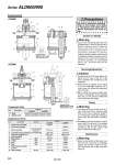
Inlet Outlet Inlet Outlet No. Description Material Aluminum casted Aluminum casted Aluminum die-casted Aluminum die-casted Body Bottom cover 1 2 ALD600 ALD900 Component Parts No. Description Material Part no. Check valve assembly Pilot body assembly Lubrication plug assembly Pressure gauge (2 pcs.) Bowl assembly Seal (2 pcs.) O-ring Seal Seal Filter element 3 4 6 7 8 9 10 11 12 14 Replacement Parts NBR NBR NBR NBR ALD600 ALD900 12612AP 126115AP GA46-10-01 AF11-3 126140 11307 126047(2) 11294-70B 12609AP 126115AP GA46-10-02 AF11-3 126060 11307 126046 126047 11294-70B 5 Bowl assembly 126139-1A 126127A 126022A 126059-1A Precautions Caution on Design Warning Mounting/Adjustment Piping Caution Warning Maintenance Warning 13 Check valve assembly (2 pcs.) Glass fiber-inserted epoxy resin Zinc die-casted, NBR Bronze ALD900 ALD600 Be sure to read before handling. Refer to front matter 43 for Safety Instructions and pages 365 to 369 for Precautions on every series. Construction 1. Epoxy resin containing glass fiber and polycarbonate is used in some parts of the D.P. Lube and the D.P. Lube Unit. These units cannot be used in an environment or in a location that is exposed to synthet ic oi l , thinner, acetone, alcohol, organic solvents such as ethylene chloride, chemicals such as sulfuric acid or nitric acid, cutting oil, kerosene, gasoline, or a threadlock agent , etc. , because they wi l l be damaged. 1. Provide about 30 cm of space above and below the D.P. Lube or the D.P. Lube Unit to facilitate their maintenance and inspection. 2. When the line is stopped, do not adjust or set the differenital pressure, as it could cause the differential adjustment valve to break. 3. When setting the pressure differential, if there is a fluctuation in the operating flow rate, set the pressure differential at the lower flow rate range. 1. The drain pipe for the air filter in the D. P. Lube Unit must have a minimum pipe bore of o6.5, and a maximum length of 5 m. Avoid using a riser pipe because it could cause the auto-drain to malfunction. 2. If installing an air tank, install it on the IN side of the D.P. Lube Unit. If it is installed on the OUT side, the micromist could be arrested by the air tank, which could lead to insufficient feeding of oil. 1. Before removing the oil filler plug, loosen it two and a half turns to completely release the pressure inside the case. This will prevent the oil filler plug from flying out. Expanded view: Mist generation nozzle (Mist generation part) Expanded view: Mist generation nozzle (Mist generation part) Mist generation part Mist generation part Series ALD600/900 958