5-p0966-0971-lmu_enü@ü@ü@4 / 7
10ĢbīŃé╔BOOKé╠āyü[āWé╔ł┌ō«éĄé▄éĘ
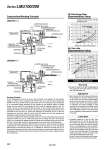
Oil filler strainer Oil filler strainer Oil level gauge Oil level gauge Construction/Working Principle Oil Discharge Rate (Representative Value) LMU100-ŁŁ LMU200-ŁŁ Of the compressed air from the air source, part is directed to the regulator for tank pressure setting (1), while the rest is directed to the ON/OFF valve for oil mist (4), which operates the ON/OFF valve for the air blow circuit (2) and the pilot valve for the mixing circuit (3). Compressed air at a prescribed setting determined by the regulator for tank pressure setting (1) passes through the fixed orifice (5) and gradually fills the oil tank (6), applying pressure to the OIL surface. The OIL in the tank passes through the strainer (7) and is drawn into the pilot valve (3). Operating the ON/OFF valve for oil mist (4) at this point will cause operating signal pressure to be conducted into the pilot valve (3), pushing the diaphragm (8) downwards, and as a result the compressed air from pilot valve (3) and oil from the opened valve will flow through their respective conduits and be drawn into the mixing valve (9). Air and oil are adjusted with varying quantities by the air for mist from the mixing valve (9) and oil adjustment needles (10) and (11). With dual piping from the mixing valve (9) to the dual pipe nozzle (12), compressed air passes through the outside while oil passes through the inside, and at the tip of the dual pipe nozzle (12) they are sprayed out as a fine mist by the discharged air. To remove cutting chips, operate the ON/OFF valve for air blow (2), which will cause the supplied compressed air to be drawn directly into the mixing valve (9) and blown out as air through the external piping of the dual pipe nozzle (12). To replenish oil, loosen the oil supply plug (14) to discharge the compressed air from inside the tank through the oil supply plugüfs side hole. Since it flows gradually from the fixed orifice (5) into the interior of the tank, it is easy to replenish oil from the oil supply hole. Mounting Handling Precautions 1. Be sure to mount an air filter corresponding to 5mm (equivalent to the SMC AF20) on the SUP side of the mist spray unit. Adjustment 1. After loosening the tanküfs pressure-setting handle (by rotating it to the left), introduce air from the air source. Use the tanküfs pressure-setting handle and set the range from 0.05 to 0.2 MPa, set each control valve to ON (manual operation or energized), and inspect carefully to make sure there is no looseness in the fittings at each connecting point. At this time, be sure the air and oil adjustment needles of the mixing valve are in a completely closed position (by rotating it to the right.) Lubrication 1. Completely release air in the OIL pipe. Even small amounts of air in the OIL pipe will cause oil to dribble. Fully open the oil adjustment needle of the mixing valve, and turn the ON/OFF valve for oil mist generation to the ON position, or press and hold down the manual button to release all air from inside the OIL pipe. If air buildup from use of branching pipes, etc. takes place inside the OIL pipe, mount an air release valve at the highest position and let the air out. Be sure to carry out this operation when replenishing the oil after the oil tank becomes empty. Conditions Oil: Turbine oil class 1 ISO VG32 Oil temperature: 26üŗC Air flow rate (Representative Value) Air flow rate L/min(ANR) Number of air needle rotations (turns) 60 50 40 30 20 10 0 0.5 1 1.5 2 2.5 3 3.5 4 0.15 MPa 0.2 MPa 0.1 MPa 0.05 MPa Number of oil needle rotations (turns) 120 100 80 60 40 20 0 0.5 1 1.5 2 2.5 3 0.1 MPa 0.05 MPa 0.15 MPa 0.2 MPa Oil tank pressure Working Principle 5 Fixed orifice 5 Fixed orifice 7 Strainer 7 Strainer Diaphragm 8 Diaphragm 8 9 Mixing valve (LMV1Ł0-Ł) 9 Mixing valve (LMV2Ł0-Ł) 4 ON/OFF valve for oil mist 4 ON/OFF valve for oil mist 3 Pilot valve 3 Pilot valve 2 ON/OFF valve for air blow Regulator for tank pressure setting 1 Regulator for tank pressure setting 1 10 Air adjusting needle for mist 10 Air adjusting needle for mist 11 Oil adjusting needle 11 Oil adjusting needle 12 Double pipe nozzle 12 Double pipe nozzle 15 Pressure gauge for tank pressure 15 Pressure gauge for tank pressure Pressure gauge for supply pressure 13 Pressure gauge for supply pressure 13 14 Lubrication plug 14 Lubrication plug Oil discharge rate cm3/min Series LMU100/200 968