5-p0972-0976-alip_en 4 / 6
10秒後にBOOKのページに移動します
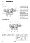
OIL IN PILOT AIR OIL OUT Steel ball Check valve (Air release knob) Check valve spring Pump chamber Piston spring Piston Handle Indicator Rubber lined FKM 4 2 1 3 5 6 7 Working Principle Construction/Parts List In the figure to the left, when pilot air enters the inlet side of the piston (1), the piston (1) overcomes the piston spring (2) and pushes oil into the pump chamber. At this time the steel ball (5) is pushed downward and closes the oil entry passage. The volume of oil in the pump chamber, equivalent to (the cross sectional area of the pump chamber intrusion piston) x (the piston stroke), pushes open the check valve (3) and is discharged from the outlet side. After the oil discharge finishes, the check valve (3) closes the outlet side passage using the check valve spring (4). After the pilot air is released, the piston (1) recovers by using the piston spring (2), the steel ball (5) is pulled upward, and new oil flows into the pump chamber from the oil entry passage. Rotate the handle (6) and change the stroke of the piston (1) to adjust the volume of oil discharged. Turning the handle left will increase the discharge volume, while turning to the right will decrease it. The movement of the piston can be confirmed visually by using the indicator (7). 3 4 5 6 7 8 9 10 11 Check spring Bonnet assembly Check spring Check valve assembly Piston spring DY seal O-ring O-ring O-ring Stainless steel . Stainless steel . Stainless steel NBR NBR NBR NBR ALIP1000-01 ALIP1100-01 . 88117-1A 881118-1 881115-2A 881117 KB00207 KA00288 KA00066 KA02133 881128 88117-3A 1 2 Body Base B Zinc die-casted Zinc die-casted Platinum silver coated Platinum silver coated 2 3 5 6 1 7 8 9 4 11 10 No. Description Material Note Main Parts List No. Description Material Part no. Spare Parts/Replacement Parts Part No. Series ALIP1000/1100 974