5-p0977-0978-aep100_en 3 / 3
10秒後にBOOKのページに移動します
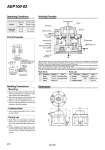
Tank Liquid collector AEP100 Silencer AN20-02 Collected fluid Nylon tube o6/4.5 Max. length 10 m o8/6 Max. length 5 m EXH IN EXH IN 86 o86 63.5 14.5 84.5 OUT Circuit Example Dimensions Mounting Collected fluid 1. Mount with the exhaust pressure IN side facing up. Mounting on a slant may result in the check valve malfunctioning. 2. Select the exhaust port side that does not require an air cylinder speed control. 3. Mount a silencer (AN20-02) on the exhaust port of the AEP100 to prevent the intrusion of dust from outside. 1. Avoid collecting spindle fluid or other corrosive fluids. During use 1. When there is no discharge of collected fluids, carry out priming from the OUT port. (This replenishes the collected fluids.) 2. Severe clogging of the gauze may result in abnormally reducing discharge volume. At such times, remove the gauze and clean it. Handling Precautions When the exhaust pressure from the switching valve enters into port u, the piston i and diaphragm y compress and displace spring r, the exhaust pressure is released into the atmosphere from exhaust port o, and at the same time the diaphragm is returned to its original condition by the recovery power of the spring. At this time, the diaphragm interior !0 is under negative pressure, causing the check ball !1 to be closed while check ball !3 is open, and causing built-up oil outside to enter into the diaphragm interior. When exhaust pressure once again enters, operation of the piston and diaphragm causes the diaphragm to be compressed, and check ball !1 opens, causing the oil in the diaphragm interior to be discharged from discharge port !2. Main Parts No. 1 2 3 Body Bonnet Gauze Spring O-ring Diaphragm assembly Description Material ADC12 ADC12 Stainless steel 304 Note Chromate treated Chromate treated Parts List No. 4 5 6 Description Material Stainless steel 304 NBR . Note 180111 JISB2401 P-40 180110A Tubing length on IN side Cylinder Bore size Stroke Piston speed o6 / o4 o8 / o6 40 mm or more 100 mm or more 100 mm/s or more 10 m or less 5 m or less Operating Conditions Working Principle AEP100-02 978