5-p0979-0980-hep500_en 3 / 3
10秒後にBOOKのページに移動します
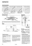
o6/4 Nylon tube Max. length / 20 m Stop valve Processing machine Pump Tank Mounting height (Max.) Water-soluble / 3 m Non-water soluble / 1 m HEP500 Strainer Leaked liquid q w e Width across flats 27 IN 1/2 1.5 35 (310) 105 32 IN OUT Nylon tube T0645 o64 IN Operating fluid Nozzle Leaked liquid suction inlet Throat part Defuser part OUT Piping Precautions 1. Install a pipe that branches off from the pipes supplying cutting oil or grinding oil to the processing machinery, and connect it to the IN side of the liquid collector. Mounting a stop valve will make maintenance easier. 2.Mount the discharge port facing in a vertical or horizontal direction. 3.When mounting the liquid collector, the mounting height is 3 m for water-soluble liquids and 1 m for non-water soluble liquids. However, the collector,s performance will decline if it is mounted in a high place, so mount the collector in as low a place as possible. 4.Use a nylon tube to connect the liquid collector with the strainer. The size should be o6 or o4.5 and length should be a maximum of 20 m, but the collector,s performance will decline as the tube gets longer, so be sure to use as short a connecting tube as possible. 5.Connect the nylon tube (200 mm) leading from the OUT side of the collector to a tank. When doing so, be sure the end of the tube does not come in contact with liquids. If this occurs, back pressure may be generated, which results in sub-optimal performance. Handling Precautions 1. The drive pressure, fluid, fluid viscosity, collection tube length, and/or pump head may affect the collected flow rate, and the liquid may not be collected or backflow to the strainer side depending on the conditions. So, use the liquid collector after checking it under operating conditions while referring to its flow characteristics. 2. During collection of leaked liquid, if there is a decline in performance, or a total failure to collect liquid occurs, check for the following potential sources of trouble. ・ When the nozzle is clogged : If the nozzle is clogged, loosen the set screw (M3 x 0.5 hexagon socket head screw), remove the nozzle from the body and clean it. ・ When the strainer gauze is clogged : After removing the C-type snap ring (nominal size 52), remove the gauze and clean it. 3. Fluids : The fluids used are water-soluble or non-water soluble. When using fluids other than these, please consult with SMC separately. When the operating fluid is released from the IN side (nozzle, throat part, defuser part) at or above a certain flow rate, it causes a collision phenomenon in the throat part and negative pressure is generated. This negative pressure is used to suck up the leaked liquid and discharge it from the OUT side along with the operating fluid, returning it to the tank. Main Parts No. 1 Body Description Material Brass Note Electroless nickel plated Parts List No. 2 3 Nozzle assembly Strainer body assembly Description Material Brass . Part no. P257021 P257014A Flow Characteristics Working Principle Dimensions Piping Non-water soluble cutting oil: Dynamic viscosity 20cSt Non-water soluble cutting oil: Dynamic viscosity 50cSt Operating pressure and operating flow rate Collection tube length 2 m 7 m 13 m 20 m Diluted water-soluble cutting oil Collected flow rate L/min Operating pressure MPa 2.0 1.6 1.2 0.8 0.4 0 0.02 0.04 0.06 0.08 0.1 Collection tube length 2 m 7 m 20 m 13 m Collected flow rate L/min Operating pressure MPa 1.0 0.8 0.6 0.4 0.2 0 0.02 0.04 0.06 0.08 0.1 Collection tube length 2 m 13 m 20 m 7 m Collected flow rate L/min Operating pressure MPa 0.5 0.4 0.3 0.2 0.1 0 0.02 0.04 0.06 0.08 0.1 Operating flow rate L/min Operating pressure MPa 5 4 3 2 1 0 0.02 0.04 0.06 0.08 0.1 Conditions: 1. Lifting range 1m 2. Collection tube (T0645) length HEP500-04 980