6-p1125-1147-izn10_enЃ@Ѓ@Ѓ@21 / 29
10•bЊг‚ЙBOOK‚МѓyЃ[ѓW‚Й€Ъ“®‚µ‚Ь‚·
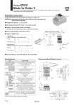
2 x 6.4 2 x 3.4 Mounting hole 8 x M3 ESD MONITOR SET OUT1 OUT2 4 3 2 1 5 6 7 8 NPN C G JQ/T IZE110-X238 56 44 6.4 38 (4.5) 11 29 34.8 21.4 16 1.5 3 x 7.2 (=21.6) . One-shot input (ON/OFF operation for a time set from trigger input) . Repeat input (ON/OFF operation during trigger input) on [Trigger] [Valve operation] off on off on [Trigger] [Valve operation] off on off SMC 10.4 16 19.4 21.4 12 35.5 3.5 34.5 р30 Series IZN10 Made to Order 2 This product is an individually applicable product. For details about the delivery time and price, please consult with SMC representative. A digital timer that can control ON/OFF switches of valves etc. Application: Improved dust removal effect under low air consumption by intermittent ion blowing Specifications Model IZE110-X238 24 VDCЃ}10% (with power supply polarity protection) 50 mA or less (Single unit only) 24 VDC 4 W or less 80 mA 30 VDC 1 V or less (At load current 80 mA) With short circuit protection (Green/Red) IP40 1000 VAC for 1 minute between terminals and housing 100 m/s2 in X, Y, Z directions 3 times each (De-energized) Front case: PBT, Rear case: Denaturated PPE 50 g Operating: 0 to 50Ѓ‹C, Stored: .10 to 60Ѓ‹C (with no freezing or condensation) Operating/Stored: 35 to 85% RH (with no condensation) 50 Mѓ¶ or more (500 VDC measured via megohmmeter), between terminals and housing 10 to 150 Hz at whichever is smaller of 1.5 mm amplitude or 20 m/s2 acceleration, in X, Y, Z direction for 2 hrs. each (De-energized) No-voltage input, Low level input 10 ms or more, Low level 0.4 V or less Power supply voltage Current consumption Connection valve OUT Note) Trigger input Indicator light Material Weight Max. load current Max. applied voltage Residual voltage Short circuit protection Enclosure Withstand voltage mpact resistance Dimensions/Input/Output circuit рЌChangeable frequency 0.1 to 50.0 Hz рЌSet individual ON and OFF times 0.1 to 99.9 seconds рЌDisplay of accumulated number of changes It can be used for maintaining valve or cylinder operation. рЌSwitch output (Output under timer control) рЌ2 types of trigger input рЌSolenoid valves up to 24 VDC (4W) etc. are controllable. GND GND OUT Valve (.) 24 VDC Trigger input Input/Output circuit Not connected 1 Valve (+) 3 4 2 8 7 6 5 Note) Do not use a load that generates surge voltage. GND Valve (+) OUT GND Solenoid valve Switch Trigger input 24V Ionizer Valve (.) [Output under timer control] Intermittent control timer Made to Order Operating temperature range Operating humidity range Environmental resistance Insulation resistance Vibration resistance Main circuit 1144