ncm 79 / 85
10秒後にBOOKのページに移動します
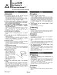
Back page 4 Series NCM Actuators Precautions 2 Be sure to read this before handling. Cushion Warning Warning 1. Readjust using the cushion needle. Cushion is adjusted at the factory, however, the cushion needle on the cover should be readjusted when the product is put into service, based upon factors such as the size of the load and the operating speed. When the cushion needle is turned clockwise, the restriction becomes smaller and the cushion's effectiveness is increased. Tighten the lock nut securely after adjustment is performed. 2. Do not operate with the cushion needle in a fully closed condition. This will cause damage to the seals. 1. Use clean air. Do not use compressed air which includes chemicals, synthetic oils containing organic solvents, salt or corrosive gases, etc., as it can cause damage or malfunction. 1. Install air filters. Install air filters at the upstream side of valves. The filtration degree should be 5 μm or finer. 2. Install an after-cooler, air dryer or water separator, etc. Air that includes excessive drainage may cause malfunction of valves and other pneumatic equipment. To prevent this, install an after-cooler, air dryer or water separator, etc. 3. Use the product within the specified range of fluid and ambient temperature. Take measures to prevent freezing, since moisture in circuits can be frozen below 5°C, and this may cause damage to seals and lead to malfunction. Refer to “Best Pneumatics 2004” Vol.14 catalog for further details on compressed air quality. 1. Removal of equipment, and supply/exhaust of compressed air. When equipment is removed, first check measures to prevent dropping of driven objects and run-away of equipment, etc. Then cut off the supply pressure and electric power, and exhaust all compressed air from the system. When machinery is restarted, proceed with caution after confirming measures to prevent cylinder from lurching. 1. Drain flushing Remove drainage from air filters regularly. (Refer to the specifications.) Mounting Caution Caution Maintenance Caution Caution Wrapping direction Pipe tape Expose approx. 2 threads 1. Be certain to align the rod axis with the load and direction of movement when connecting. When not properly aligned, the rod and tube may be twisted, and damage may be caused due to wear on areas such as the inner tube surface, bushings, rod surface and seals. 2. When an external guide is used, connect the rod end and the load in such a way that there is no interference at any point within the stroke. 3. Do not scratch or gouge the sliding parts of the cylinder tube or piston rod, etc., by striking or grasping them with other objects. Cylinder bores are manufactured to precise tolerances, so that even a slight deformation may cause malfunction. Also, scratches or gouges, etc., in the piston rod may lead to damaged seals and cause air leakage. 4. Prevent the seizure of rotating parts. Prevent the seizure of rotating parts (pins, etc.) by applying grease. 5. Do not use until you can verify that equipment can operate properly. Verify correct mounting by appropriate function and leakage inspections after compressed air and power are connected following mounting, maintenance or conversions. 6. Instruction manual The product should be mounted and operated after thoroughly reading the manual and understanding its contents. Keep the instruction manual where it can be referred to as needed. 7. Preparation before piping Before piping is connected, it should be thoroughly blown out with air (flushing) or washed to remove chips, cutting oil and other debris from inside the pipe. 8. Wrapping of pipe tape When screwing together pipes and fittings, etc., be certain that chips from the pipe threads and sealing material do not get inside the piping. Also, when pipe tape is used, leave 1.5 to 2 thread ridges exposed at the end of the threads. 9. Mount an auto switch at the center of the operating range. Adjust the mounting position of an auto switch so that the piston stops at the center of the operating range (the range in which a switch is ON). (The mounting position shown in the catalog indicates the optimum position at stroke end.) If mounted at the end of the operating range (around the borderline of ON and OFF), operation will be unstable.