12-e601-lefs 11 / 29
10秒後にBOOKのページに移動します
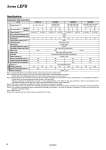
Specifications Step Motor (Servo/24 VDC) Model LEFS16 LEFS25 LEFS32 LEFS40 Actuator specifications Stroke [mm] Note 1) 100, 200, 300, 400 100, 200, 300 400, 500, 600 100, 200, 300, 400 500, 600, 700, 800 200, 300, 400, 500, 600 700, 800, 900, 1000 Work load [kg] Note 2) Horizontal 9 10 20 20 40 45 50 60 Vertical 2 4 7.5 15 10 20 . 23 Speed [mm/s] Note 2) 10 to 500 5 to 250 12 to 500 6 to 250 16 to 500 8 to 250 20 to 500 10 to 250 Max. acceleration/deceleration [mm/s2] 3,000 Positioning repeatability [mm] ±0.02 Lead [mm] 10 5 12 6 16 8 20 10 Impact/Vibration resistance [m/s2] Note 3) 50/20 Actuation type Ball screw + Belt Guide type Linear guide Operating temperature range [°C] 5 to 40 Operating humidity range [%RH] 90 or less (No condensation) Electric specifications Motor size 28 42 56.4 Motor type Step motor (Servo/24 VDC) Encoder Incremental A/B phase (800 pulse/rotation) Rated voltage [V] 24 VDC ±10% Power consumption [W] Note 4) 22 38 50 100 Standby power consumption when operating [W] Note 5) 18 16 44 43 Max. instantaneous power consumption [W] Note 6) 51 57 123 141 Lock unit specifications Type Note 7) Non-magnetizing lock Holding force [N] 20 39 78 157 108 216 113 225 Power consumption [W] Note 8) 2.9 5 5 5 Rated voltage [V] 24 VDC ±10% Note 1) Consult with SMC for non-standard strokes as they are produced as special orders. Note 2) Speed changes according to the work load. Check “Speed.Work Load Graph (Guide)” on page 2. Furthermore, if the cable length exceeds 5 m, then it will decrease by up to 10% for each 5 m. Note 3) Impact resistance: No malfunction occurred when the actuator was tested with a drop tester in both an axial direction and a perpendicular direction to the lead screw. (Test was performed with the actuator in the initial state.) Vibration resistance: No malfunction occurred in a test ranging between 45 to 2000 Hz. Test was performed in both an axial direction and a perpendicular direction to the lead screw. (Test was performed with the actuator in the initial state.) Note 4) The power consumption (including the controller) is for when the actuator is operating. Note 5) The standby power consumption when operating (including the controller) is for when the actuator is stopped in the set position during the operation. Note 6) The maximum instantaneous power consumption (including the controller) is for when the actuator is operating. This value can be used for the selection of the power supply. Note 7) With lock only Note 8) For an actuator with lock, add the power consumption for the lock. 9 Series LEFS A