12-e601-lefs 15 / 29
10秒後にBOOKのページに移動します
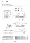
Body mounting reference plane Note 1) With lock: LEFS25𡱖𡱖-𡱖B Motor mounting position: Left side parallel LEFS25L𡱖 Motor mounting position: Right side parallel LEFS25R𡱖 Connector Motor cable Lock cable o3H9 ( ) depth 3 3H9 ( ) depth 3 + 0.025 0 3H9 ( ) depth 3 + 0.025 0 24 24 20 20 20 15 20 15 Cable length . 400 65 Lock cable (o3.5) Motor cable (2 x o5) Cable length . 250 109 125.5 65 (2.4) 7.5 47 46 106 106 46 47 38 106 Cable length . 250 7.5 Motor cable (2 x o5) 68.5 85 (2.4) 65 4 x M5 x 0.8 thread depth 8.5 50 (102) 64 45 3.5 L A (Table traveling distance) Note 2) Stroke 52 40.5 54 [(56)] Note 4) 2 [(4)] Note 4) 10 (52) (56) [54] Note 4) (4) [2] Note 4) [Origin] Note 4) Origin Note 3) 38.5 48 M4 x 0.7 thread depth 8 (F.G. terminal) 48 24 58 46 38 45.9 (7.5) 6.5 6 n x o4.5 120 D x 120 (= E) B 35 48 10 4 Step motor Servo motor + 0.025 0 Dimensions: Ball Screw Drive Motor right side parallel type: LEFS25R (mm) Model L A B n D E LEFS25𡱖𡱖-100𡱖-𡱖𡱖𡱖𡱖𡱖 260.5 106 210 4 . . LEFS25𡱖𡱖-200𡱖-𡱖𡱖𡱖𡱖𡱖 360.5 206 310 6 2 240 LEFS25𡱖𡱖-300𡱖-𡱖𡱖𡱖𡱖𡱖 460.5 306 410 8 3 360 LEFS25𡱖𡱖-400𡱖-𡱖𡱖𡱖𡱖𡱖 560.5 406 510 8 3 360 LEFS25𡱖𡱖-500𡱖-𡱖𡱖𡱖𡱖𡱖 660.5 506 610 10 4 480 LEFS25𡱖𡱖-600𡱖-𡱖𡱖𡱖𡱖𡱖 760.5 606 710 12 5 600 Note 1) When mounting the actuator using the body mounting reference plane, set the height of the opposite surface or pin to be 3 mm or more. (Recommended height 5 mm) Note 2) Distance within which the table can move when it returns to origin. Make sure a workpiece mounted on the table does not interfere with the workpieces and facilities around the table. Note 3) Position after return to origin. Note 4) The number in brackets indicates when the direction of return to origin has changed. 13 Series LEFS