12-e601-lefs 25 / 29
10秒後にBOOKのページに移動します
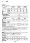
Weight Specifications LEFS25, 32, 40 AC Servo Motor Model LEFS25S LEFS32S LEFS40S Actuator specifications Stroke [mm] Note 1) 100, 200, 300, 400 500, 600 100, 200, 300, 400 500, 600, 700, 800 200, 300, 400, 500 600, 700, 800, 900 1000 Work load [kg] Note 2) Horizontal 20 20 40 45 50 60 Vertical 8 15 10 20 15 30 Max. speed Note 3) [mm/s] Stroke range Up to 400 900 450 1000 500 1000 500 401 to 500 720 360 1000 500 1000 500 501 to 600 540 270 800 400 1000 500 601 to 700 . . 620 310 940 470 701 to 800 . . 500 250 760 380 801 to 900 . . . . 620 310 901 to 1000 . . . . 520 260 Max. acceleration/deceleration [mm/s2] 20,000 (Refer to page 17 for limit according to work load and duty ratio.) Positioning repeatability [mm] ±0.02 Lead [mm] 12 6 16 8 20 10 Impact/Vibration resistance [m/s2] Note 4) 50/20 Actuation type Ball screw + Belt Guide type Linear guide Operating temperature range [°C] 5 to 40 Operating humidity range [%RH] 90 or less (No condensation) Electric specifications Motor output/Size 100 W/40 200 W/60 400 W/60 Motor type AC servo motor (100/200 VAC) Encoder Motor type S2, S3, S4: Incremental 17-bit encoder (Resolution: 131072 p/rev) Motor type S6, S7, S8: Absolute 18-bit encoder (Resolution: 262144 p/rev) Power consumption [W] Note 5) Horizontal 45 65 210 Vertical 145 175 230 Standby power consumption when operating [W] Note 6) Horizontal 2 2 2 Vertical 8 8 18 Max. instantaneous power consumption [W] Note 7) 445 725 1275 Lock unit specifications Type Note 8) Non-magnetizing lock Holding force [N] 131 255 197 385 330 660 Power consumption [W] at 20°C Note 9) 6.3 7.9 7.9 Rated voltage [V] 24 VDC Note 1) Consult with SMC for non-standard strokes as they are produced as special orders. Note 2) For details, refer to “Speed.Work Load Graph (Guide)” on page 17. Note 3) The allowable speed changes according to the stroke. Note 4) Impact resistance: No malfunction occurred when the actuator was tested with a drop tester in both an axial direction and aperpendicular direction to the lead screw. (Test was performed with the actuator in the initial state.) Vibration resistance: No malfunction occurred in a test ranging between 45 to 2000 Hz. Test was performed in both an axial direction and a perpendicular direction to the lead screw. (Test was performed with the actuator in the initial state.) Note 5) The power consumption (including the driver) is for when the actuator is operating. Note 6) The standby power consumption when operating (including the driver) is for when the actuator is stopped in the set position during the operation. Note 7) The maximum instantaneous power consumption (including the driver) is for when the actuator is operating. Note 8) Only when motor option “With lock” is selected. Note 9) For an actuator with lock, add the power consumption for the lock. 26 37 48 0 .10% Model LEFS40 Stroke [mm] 200 300 400 500 600 700 800 900 1000 Product weight [kg] 5.15 5.71 6.27 6.83 7.39 7.95 8.51 9.07 9.63 Additional weight with lock [kg] 0.61 Model LEFS25 Stroke [mm] 100 200 300 400 500 600 Product weight [kg] 1.79 2.07 2.35 2.63 2.91 3.19 Additional weight with lock [kg] 0.29 Model LEFS32 Stroke [mm] 100 200 300 400 500 600 700 800 Product weight [kg] 3.25 3.65 4.05 4.45 4.85 5.25 5.65 6.05 Additional weight with lock [kg] 0.64 23 Series LEFS A