es20-223-cm2 23 / 122
10秒後にBOOKのページに移動します
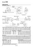
NA MM NN oD oE G H A K F AL H1 LP L G U RR oCD oCI LF LG LY LT NA LH LV CX oI Width across flats KA 2 x P (Rc, NPT, G) Effective thread length FL 2 x oLD Width across flats B1 LZ + Stroke ZZ + Stroke Z + Stroke S + Stroke Refer to page 23 for details of clevis pivot bracket. +0.058 .0 +0.1 .0.1 JH oe f JW h l WA WA ZZ + Stroke 8 8 Width across flats B3 45° Cushion needle (Width across flats 1.5) Port H ZZ + Stroke Female thread MM Thread depth A1 3.5 CM2E Bore size . Stroke Z Integral Clevis (E) Integral clevis (90°)(V) With rod boot With air cushion * The dimensions are the same as those for the integral clevis (E). With Rod Boot (mm) B3 e f h 1 to 50 51 to 100 101 to 150 151 to 200 201 to 300 301 to 400 401 to 500 20 30 36 18 68 81 93 106 131 156 181 25 32 36 18 72 85 97 110 135 160 185 32 32 36 18 72 85 97 110 135 160 185 40 41 46 20 77 90 102 115 140 165 190 Bore size Stroke Symbol Clevis Pivot Bracket (mm) Bore size LD LF LG LH LP LT LV LY LZ 20 6.8 15 30 30 37 3.2 18.4 59 152 25 6.8 15 30 30 37 3.2 18.4 59 156 32 9 15 40 40 50 4 28 75 174 40 9 15 40 40 50 4 28 75 203 (mm) Bore size P RR S U Z ZZ 20 1/8 9 62 11.5 115 124 25 1/8 9 62 11.5 119 128 32 1/8 12 64 14.5 124 136 40 1/4 12 88 14.5 153 165 With Air Cushion (mm) Bore size WA 20 12 25 12 32 11 40 16 * When female thread is used, use a thin wrench when tightening the piston rod. * When female thread is used, use a washer etc. to prevent the contact part at the rod end from being deformed depending on the material of the workpiece. Female Rod End (mm) Bore size A1 H MM ZZ 20 8 20 M4 x 0.7 103 25 8 20 M5 x 0.8 103 32 12 20 M6 x 1 111 40 13 21 M8 x 1.25 136 (mm) Bore size A AL B1 CD CI CX D E F FL G H H1 I K KA L MM NA NN 20 18 15.5 13 8 20 12 8 20 0 .0.033 13 10.5 8 41 5 28 5 6 12 M8 x 1.25 24 M20 x 1.5 25 22 19.5 17 8 22 12 10 26 0 .0.033 13 10.5 8 45 6 33.5 5.5 8 12 M10 x 1.25 30 M26 x 1.5 32 22 19.5 17 10 27 20 12 26 0 .0.033 13 10.5 8 45 6 37.5 5.5 10 15 M10 x 1.25 34.5 M26 x 1.5 40 24 21 22 10 33 20 14 32 0 .0.039 16 13.5 11 50 8 46.5 7 12 15 M14 x 1.5 42.5 M32 x 2 With Rod Boot l Z ZZ JH JW 1 to 50 51 to 100 101 to 150 151 to 200 201 to 300 301 to 400 401 to 500 1 to 50 51 to 100 101 to 150 151 to 200 201 to 300 301 to 400 401 to 500 1 to 50 51 to 100 101 to 150 151 to 200 201 to 300 301 to 400 401 to 500 20 12.5 25 37.5 50 75 100 125 142 155 167 180 205 230 255 151 164 176 189 214 239 264 23.5 10.5 25 12.5 25 37.5 50 75 100 125 146 159 171 184 209 234 259 155 168 180 193 218 243 268 23.5 10.5 32 12.5 25 37.5 50 75 100 125 151 164 176 189 214 239 264 163 176 188 201 226 251 276 23.5 10.5 40 12.5 25 37.5 50 75 100 125 180 193 205 218 243 268 293 192 205 217 230 255 280 305 27 10.5 Bore size Stroke Symbol (mm) Female rod end 21 Series CM2