es20-223-cm2 39 / 122
10秒後にBOOKのページに移動します
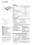
Single knuckle joint Single clevis Auto switch Pivot bracket * The shape is the same as the existing product. Spring extend Spring return Single acting, Spring extend, Rubber bumper Single acting, Spring return, Rubber bumper Symbol Bore size (mm) 20 25 32 40 Action Single acting, Spring return/Single acting, Spring extend Type Pneumatic Cushion Rubber bumper Fluid Air Proof pressure 1.5 MPa Maximum operating pressure 1.0 MPa Minimum operating pressure Single acting, Spring return 0.18 MPa Single acting, Spring extend 0.23 MPa Ambient and fluid temperature Without auto switch: .10°C to 70°C (No freezing) With auto switch: .10°C to 60°C Lubrication Not required (Non-lube) Stroke length tolerance +1.4 0 mm Piston speed 50 to 750 mm/s Allowable kinetic energy Male thread 0.27 J 0.4 J 0.65 J 1.2 J Female thread 0.11 J 0.18 J 0.29 J 0.52 J Symbol Specifications -XAl Change of rod end shape -XB12 External stainless steel cylinder* -XC3 Special port location -XC6 Made of stainless steel -XC13 Auto switch rail mounting -XC20 Head cover axial port -XC25 No fixed throttle of connection port -XC27 Double clevis and double knuckle pins made of stainless steel -XC29 Double knuckle joint with spring pin -XC52 Mounting nut with set screw -XC85 Grease for food processing equipment Specifications Mounting Bracket For the mounting bracket part numbers other than basic type, refer to page 38. Spring Reaction Force Refer to the WEB catalog or the Best Pneumatics No. 2 (Table (3): Spring Reaction Force). Accessories Refer to pages 22 and 23 for accessories, since it is the same as standard type, double acting, single rod. Theoretical Output Refer to the WEB catalog or the Best Pneumatics No. 2 (Theoretical Output 1). Bore size (mm) Standard stroke (mm) Note 1) 20 25, 50, 75, 100, 125, 150 25 25, 50, 75, 100, 125, 150 32 25, 50, 75, 100, 125, 150, 200 40 25, 50, 75, 100, 125, 150, 200, 250 Note 1) Other intermediate strokes can be manufactured upon receipt of order. Manufacture of intermediate strokes at 1 mm intervals is possible. (Spacers are not used.) Note 2) Applicable strokes should be confirmed according to the usage. For details, refer to “Air Cylinders Model Selection” on front matter pages of the Best Pneumatics No. 2 or the WEB catalog. In addition, the products that exceed the standard stroke might not be able to fulfill the specifications due to the deflection etc. Note 3) Please consult with SMC for strokes which exceed the standard stroke length. Standard Strokes Refer to pages 95 to 99 for cylinders with auto switches. . Auto switch proper mounting position (detection at stroke end) and its mounting height . Minimum stroke for auto switch mounting . Operating range . Auto switch mounting brackets/Part no. Made to Order (For details, refer to pages 101 to 117.) Option: Ordering Example of Cylinder Assembly Mounting C: Single clevis Pivot bracket N: Yes Rod end bracket V: Single knuckle joint Auto switch D-M9BW: 2 pcs. * Pivot bracket, single knuckle joint and auto switch are shipped together with the product, but not assembled. * Pivot bracket is available only for C, T, U, E, V, UZ mounting types. * No bracket is provided for the female rod end. Cylinder model: CDM2C32-150SZ-NV-M9BW 37 Series CM2