es20-223-cm2 67 / 122
10秒後にBOOKのページに移動します
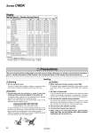
Precautions Be sure to read this before handling. Refer to the back cover for Safety Instructions. For Actuator and Auto Switch Precautions, refer to “Handling Precautions for SMC Products” and the Operation Manual on SMC website, http://www.smcworld.com Warning Handling Caution Caution 1. Do not rotate the cover. If a cover is rotated when installing a cylinder or screwing a fitting into the port, it is likely to damage the junction part with cover. 2. When replacing rod seals, please contact SMC. Air leakage may be happened, depending on the position in which a rod seal is fitted. Thus, please contact SMC when replacing them. 3. Not able to disassemble. Cover and cylinder tube are connected to each other by caulking method, thus making it impossible to disassemble. Therefore, internal parts of a cylinder other than rod seal are not replaceable. 4. Do not touch the cylinder during operation. Use caution when handling a cylinder, which is running at a high speed and a high frequency, because the surface of a cylinder tube could get so hot enough as to cause you get burned. 5. The oil stuck to the cylinder is grease. 6. The base oil of grease may seep out. 7. When using a rod end bracket and/or pivot bracket, make sure they do not interfere with other brackets, workpieces and rod section, etc. 1. Avoid using the air cylinder in such a way that rotational torque would be applied to the piston rod. If rotational torque is applied, the non-rotating guide will become deformed, thus affecting the non-rotating accuracy. Refer to the table below for the approximate values of the allowable range of rotational torque. To screw a bracket or a nut onto the threaded portion at the tip of the piston rod, make sure to retract the piston rod entirely, and place a wrench over the flat portion of the rod that protrudes. Tighten it by giving consideration to prevent the tightening torque from being applied to the non-rotating guide. Allowable rotational torque (N・m or less) o20 o25 o32 o40 0.2 0.25 0.25 0.44 Bore size (mm) 20 25 32 40 Basic weight 25 stroke 0.20 (0.19) 0.31 (0.30) 0.43 (0.41) 0.78 (0.75) 50 stroke 0.23 (0.21) 0.34 (0.33) 0.48 (0.45) 0.86 (0.83) 75 stroke 0.29 (0.25) 0.43 (0.41) 0.61 (0.56) 1.08 (0.99) 100 stroke 0.31 (0.27) 0.47 (0.44) 0.66 (0.60) 1.14 (1.06) 125 stroke 0.37 (0.32) 0.56 (0.52) 0.81 (0.72) 1.34 (1.23) 150 stroke 0.39 (0.34) 0.59 (0.55) 0.85 (0.76) 1.39 (1.31) 200 stroke . (.) . (.) 1.04 (0.92) 1.71 (1.54) 250 stroke . (.) . (.) . (.) 2.00 (1.78) Mounting brackets Foot 0.15 (0.15) 0.16 (0.16) 0.16 (0.16) 0.27 (0.27) Flange 0.06 (0.06) 0.09 (0.09) 0.09 (0.09) 0.12 (0.12) Single clevis 0.04 (0.04) 0.04 (0.04) 0.04 (0.04) 0.09 (0.09) Double clevis 0.05 (0.05) 0.06 (0.06) 0.06 (0.06) 0.13 (0.13) Trunnion 0.04 (0.04) 0.07 (0.07) 0.07 (0.07) 0.10 (0.10) Integral clevis .0.02 (.0.02) .0.02 (.0.02) .0.01 (.0.01) .0.04 (.0.04) Boss-cut/Basic .0.01 (.0.01) .0.02 (.0.02) .0.02 (.0.02) .0.03 (.0.03) Boss-cut/Flange 0.05 (0.05) 0.07 (0.07) 0.07 (0.07) 0.09 (0.09) Boss-cut/Trunnion 0.03 (0.03) 0.05 (0.05) 0.05 (0.05) 0.07 (0.07) Option bracket Clevis pivot bracket (with pin) 0.07 (0.07) 0.07 (0.07) 0.14 (0.14) 0.14 (0.14) Single knuckle joint 0.06 (0.06) 0.06 (0.06) 0.06 (0.06) 0.23 (0.23) Double knuckle joint (with pin) 0.07 (0.07) 0.07 (0.07) 0.07 (0.07) 0.20 (0.20) Calculation (Example) CM2KL32-100SZ (Bore size o32, Foot, 100 stroke) 0.66 (Basic weight) + 0.16 (Mounting bracket weight) = 0.82 kg Spring Return/( ): Denotes Spring Extend. (kg) Weights 65 Series CM2K