es20-223-cm2 95 / 122
10秒後にBOOKのページに移動します
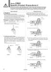
Rubber cap Unlock Lock Spring Lock piston Pressure Piston rod . Back pressure Pressure Exhaust Exhaust Series CBM2 Specific Product Precautions 2 Be sure to read this before handling. Refer to the back cover for Safety Instructions. For Actuator and Auto Switch Precautions, refer to “Handling Precautions for SMC Products” and the Operation Manual on SMC website, http://www.smcworld.com Manual Release Working Principle Caution 1. Non-locking type manual release Insert the accessory bolt from the top of the rubber cap (it is not necessary to remove the rubber cap), and after screwing it into the lock piston, pull it to release the lock. If you stop pulling the bolt, the lock will return to an operational state. Thread sizes, pulling forces and strokes are as shown below. Remove the bolt for normal operation. It can cause lock malfunction or faulty release. 2. Locking type manual release While pushing the M/O knob, turn it 90° counterclockwise. The lock is released (and remains in a released state) by aligning the G mark on the cap with the HOFF mark on the M/O knob. When locking is desired, turn M/O knob clockwise 90° while pushing fully, correspond G mark on cap and HON mark on M/O knob. The correct position is confirmed by a clicking sound. If not confirmed, locking is not done. PHead end lock (Rod end lock is the same, too.) 1. When the piston rod is getting closer to the stroke end, the taper part (*) of the piston rod edge will push the lock piston up. 4. When pressure is supplied in the head side, lock piston will be pushed up to release the lock. 5. Lock will be released, then cylinder will move forward. 2. Lock piston is pushed up further. 3. Lock piston is pushed up into the groove of piston rod to lock it. (Lock piston is pushed up by spring force.) At this time, it is exhausted from port in head side and introduced to atmosphere. The figures below are the same as those for Series CBA2. Locked Locked Released Released Bore size (mm) Thread size Pulling force Stroke (mm) 20, 25, 32 M2.5 x 0.45 x 25 L or more 4.9 N 2 40 M3 x 0.5 x 30 L or more 10 N 3 93