es20-224-cg1Ā@Ā@Ā@12 / 96
10ēbĆ„ā…BOOKāŐÉyĀ[ÉWā…ąŕďģāĶā‹ā∑
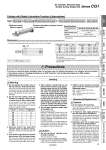
GA 2 x P Caution 1. Do not replace the bushings. The bushings are press-fit. To replace them, they must be replaced together with the cover assembly. 2. To replace a seal, apply grease to the new seal before installing it. If the cylinder is put into operation without applying grease to the seal, it could cause the seal to wear significantly, leading to premature air leakage. 3. Cylinders with o50 or larger bore sizes cannot be disassembled. When disassembling cylinders with bore sizes of o20 through o40, grip the double flat part of either the tube cover or the rod cover with a vise and loosen the other side with a wrench or a monkey wrench etc., and then remove the cover. When retightening, tighten approximately 2 degrees more than the original position. (Cylinders with o50 or larger bore sizes are tightened with a large tightening torque and cannot be disassembled. I f disassembly is required, please contact SMC.) Disassembly/Replacement Warning 1. Do not operate the cushion valve in the fully closed or fully opened state. Using it in the fully closed state will cause the cushion seal to be damaged. Using it in the fully opened state will cause the piston rod assembly or the cover to be damaged. 2. Do not turn the cushion valve the number of rotations shown below or more from its fully closed state. If it is turned the number of rotations shown below or more, the cushion valve may come off and jump out by the air pressure, causing a hazard. Bore size (mm) Rotations Hexagon wrench nominal size 20 2 1.5 25 3 1.5 32 4 1.5 40 5 1.5 50 3 3 63 4.5 3 80 5 4 100 5 4 3. Operate wi thin the speci f ied cylinder speed and kinetic energy. Otherwise, cylinder and seal damage may occur. 4. Use caution regarding the cushion performance in the low-speed range. There may be individual performance and effect variances when used near 50 mm/ s. Please consult with SMC about usage. Handling 5. When a cylinder is operated with one end fixed and other free (basic, flange types), a bending moment may act on the cylinder due to the vibration generated at the stroke end, which can damage the cylinder. In such a case, install a mounting bracket to suppress the vibration of the cylinder body or reduce the piston speed so that the cylinder does not vibrate. Also, use a mounting bracket to suppress vibrations when moving the cylinder body or when a cylinder is operated horizontally and fixed at one end at a high speed and frequency. 6. Do not apply excessive lateral load to the piston rod. Easy checking method Minimum operating pressure after the cylinder is mounted to the equipment (MPa) = Minimum operating pressure of cylinder (MPa) + {Load weight (kg) x 9.8 x Friction coefficient of guide/Sectional area of cylinder (mm2)} If smooth operation is confirmed within the above value, the load on the cylinder is the resistance of the thrust only and it can be judged as having no lateral load. Caution 1. Do not use the air cylinder as an air-hydro cylinder. This may result in oil leak. 2. Install a rod boot without twisting. If the cylinder is installed with its bellows twisted, it could damage the bellows. 3. Tighten clevis bracket mounting bolts with the following proper tightening torque. o20: 1.5 NĀEm, o25 to 32: 2.9 NĀEm, o40: 4.9 NĀEm, o50: 11.8 NĀEm, o63 to 80: 24.5 NĀEm, o100: 42.2 NĀEm Be sure to read this before handling. Refer to the back cover for Safety Instructions. For Actuator and Auto Switch Precautions, refer to ĀgHandling Precautions for SMC ProductsĀh and the Operation Manual on SMC website, http://www.smcworld.com Precautions Cylinder with Stable Lubrication Function (Lube-retainer) M Refer to the WEB catalog for details. * No trunnion mounting female thread is provided on the rod side. (For B: Basic) Dimensions (Dimensions other than those shown below are the same as the standard type.) CDG1 Bore size Stroke Rod end thread Z Rod end bracket Auto switch With auto switch (Built-in magnet) Mounting Z Pivot bracket Cylinder with Stable Lubrication Function (Lube-retainer) Specifications Bore size (mm) 20, 25, 32, 40, 50, 63, 80, 100 Action Double acting, Single rod Minimum operating pressure 0.1 MPa Cushion Rubber bumper * Specifications other than the above are the same as the standard type. (mm) Bore size GA P Bore size GA P 20 14 M5 x 0.8 50 (14) (Rc 1/4) 25 13 M5 x 0.8 63 (14) (Rc 1/4) 32 (12) (Rc 1/8) 80 (20) (Rc 3/8) 40 (13) (Rc 1/8) 100 (20) (Rc 1/2) * When female thread is used, use a washer, etc. to prevent the contact part at the rod end from being deformed depending on the material of the workpiece. ( ): Same as the standard model. * The mounting dimensions of the mounting bracket are the same as the standard type. 10 Air Cylinder: Standard Type Double Acting, Single Rod Series CG1 CG1ūģQ CBG1 CG1KR CG1R CG1KW CG1K CG1 CG1W CG1 Low Friction With End Lock Direct Mount, Non-rotating Rod Direct Mount Non-rotating Rod Standard Double Acting, Single Rod Double Acting, Single Rod Double Acting, Double Rod Double Acting, Single Rod Single Acting, Spring Return/Extend Double Acting, Double Rod Double Acting, Single Rod Made to Order Auto Switch