es20-224-cg1 17 / 96
10秒後にBOOKのページに移動します
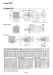
oI oD l l F FT GA GB AL A H F K GA WA GB WB JW JH oe oIJ f oe oIJ f h + l 8 8 8 10° Wθ° ZZ + l + Stroke ZZ + l + Stroke h + l 0 oE.0.05 0 .oE.0.05 ZZ + Stroke S + Stroke Width across flats NA Width across flats B1 B FX±0.15 C C FX±0.15 B 4 x oFD 8 x J MM H1 Width across flats KA 2 x P (Rc, NPT, G) R0.4 2 x P (Rc, NPT, G) Cushion valve, Width across flats WH Rod Flange: CG1FN With air cushion With rod boot * End boss is machined on the flange for oE. o80, o100 * For female rod end, since the wrench flap (K and KA portions) will be inside of the bracket when the piston rod is retracted at the stroke end, extend the piston rod to tighten the nut using a tool, and mount a workpiece on the rod end. * Refer to the basic type for the female rod end. Note) ( ): Denotes the dimensions for long stroke. * The minimum stroke with rod boot is 20 mm. (mm) (mm) (mm) (mm) With Air Cushion With Rod Boot Bore size Stroke range Rc, NPT port G port A AL B B1 C D E F FD FT FX H H1 I J K Standard Long stroke GA GB P GA GB P 20 Up to 200 201 to 1500 12 10 (12) 1/8 12 10 (12) M5 x 0.8 18 15.5 40 13 14 8 12 2 5.5 6 28 35 5 26 M4 x 0.7 5 25 Up to 300 301 to 1500 12 10 (12) 1/8 12.5 10 (12.5) M5 x 0.8 22 19.5 44 17 16.5 10 14 2 5.5 7 32 40 6 31 M5 x 0.8 5.5 32 Up to 300 301 to 1500 12 10 (12) 1/8 10.5 10 (10.5) 1/8 22 19.5 53 17 20 12 18 2 6.6 7 38 40 6 38 M5 x 0.8 5.5 40 Up to 300 301 to 1500 13 10 (13) 1/8 13 10 (10) 1/8 30 27 61 19 26 16 25 2 6.6 8 46 50 8 47 M6 x 1 6 50 Up to 300 301 to 1500 14 12 (14) 1/4 14 12 (14) 1/4 35 32 76 27 32 20 30 2 9 9 58 58 11 58 M8 x 1.25 7 63 Up to 300 301 to 1500 14 12 (14) 1/4 14 12 (14) 1/4 35 32 92 27 38 20 32 2 11 9 70 58 11 72 M10 x 1.5 7 80 Up to 300 301 to 1500 20 16 (20) 3/8 17.5 16 (17.5) 3/8 40 37 104 32 50 25 40 3 11 11 82 71 13 89 M10 x 1.5 10 100 Up to 300 301 to 1500 20 16 (20) 1/2 17.5 16 (17.5) 1/2 40 37 128 41 60 30 50 3 14 14 100 71 16 110 M12 x 1.75 10 Bore size KA MM NA S ZZ 20 6 M8 x 1.25 24 69 (77) 106 (114) 25 8 M10 x 1.25 29 69 (77) 111 (119) 32 10 M10 x 1.25 35.5 71 (79) 113 (121) 40 14 M14 x 1.5 44 78 (87) 130 (139) 50 18 M18 x 1.5 55 90 (102) 150 (162) 63 18 M18 x 1.5 69 90 (102) 150 (162) 80 22 M22 x 1.5 86 108 (122) 182 (196) 100 26 M26 x 1.5 106 108 (122) 182 (196) Bore size Rc, NPT, G GA GB P WA WB Wθ WH 20 12 10 (12) M5 x 0.8 16 15 (16) 25° 1.5 25 12.5 10 (12.5) M5 x 0.8 16 14.5 (16) 25° 1.5 32 12 10 (12) 1/8 16 14 (16) 25° 1.5 40 13 10 (13) 1/8 17 15 (17) 20° 1.5 50 14 12 (14) 1/4 18 16 (18) 20° 3 63 14 12 (14) 1/4 18 17 (18) 20° 3 80 20 16 (20) 3/8 24 20 (24) 20° 4 100 20 16 (20) 1/2 24 20 (24) 20° 4 Bore size e f h IJ JH (Reference) JW (Reference) l ZZ 20 30 18 55 27 15.5 10.5 1/4 stroke 126 (134) 25 30 19 62 32 16.5 10.5 133 (141) 32 35 19 62 38 18.5 10.5 135 (143) 40 35 19 70 48 21.5 10.5 150 (159) 50 40 19 78 59 24 10.5 170 (182) 63 40 20 78 72 24 10.5 170 (182) 80 52 10 80 59 . . 191 (205) 100 62 7 80 71 . . 191 (205) 15 Series CG1