es20-224-cg1ü@ü@ü@18 / 96
10ĢbīŃé╔BOOKé╠āyü[āWé╔ł┌ō«éĄé▄éĘ
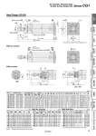
oD oI l l H1 F GA GB AL A H K FT F C B B C GA WA GB WB JW JH oe oIJ f oe oIJ f FXü}0.15 FXü}0.15 4 x oFD 8 x J ZZ + Stroke S + Stroke 0 oE.0.05 . 0 oE.0.05 MM Width across flats KA 2 x P (Rc, NPT, G) Width across flats B1 Width across flats NA R0.4 ZZ + l + Stroke h + l 8 8 8 ZZ + l + Stroke h + l 10üŗ WāŲüŗ Cushion valve, Width across flats WH 2 x P (Rc, NPT, G) Head Flange: CG1GN With air cushion With rod boot * End boss is machined on the flange for oE. o80, o100 * Refer to the basic type for the female rod end. Note) ( ): Denotes the dimensions for long stroke. * The minimum stroke with rod boot is 20 mm. (mm) With Air Cushion (mm) With Rod Boot (mm) (mm) Bore size Stroke range Rc, NPT port G port A AL B B1 C D E F FD FT FX H H1 I J K Standard Long stroke GA GB P GA GB P 20 Up to 200 201 to 1500 12 10 (12) 1/8 12 10 (12) M5 x 0.8 18 15.5 40 13 14 8 12 2 5.5 6 28 35 5 26 M4 x 0.7 5 25 Up to 300 301 to 1500 12 10 (12) 1/8 12.5 10 (12.5) M5 x 0.8 22 19.5 44 17 16.5 10 14 2 5.5 7 32 40 6 31 M5 x 0.8 5.5 32 Up to 300 301 to 1500 12 10 (12) 1/8 10.5 10 (10.5) 1/8 22 19.5 53 17 20 12 18 2 6.6 7 38 40 6 38 M5 x 0.8 5.5 40 Up to 300 301 to 1500 13 10 (13) 1/8 13 10 (10) 1/8 30 27 61 19 26 16 25 2 6.6 8 46 50 8 47 M6 x 1 6 50 Up to 300 301 to 1500 14 12 (14) 1/4 14 12 (14) 1/4 35 32 76 27 32 20 30 2 9 9 58 58 11 58 M8 x 1.25 7 63 Up to 300 301 to 1500 14 12 (14) 1/4 14 12 (14) 1/4 35 32 92 27 38 20 32 2 11 9 70 58 11 72 M10 x 1.5 7 80 Up to 300 301 to 1500 20 16 (20) 3/8 17.5 16 (17.5) 3/8 40 37 104 32 50 25 40 3 11 11 82 71 13 89 M10 x 1.5 10 100 Up to 300 301 to 1500 20 16 (20) 1/2 17.5 16 (17.5) 1/2 40 37 128 41 60 30 50 3 14 14 100 71 16 110 M12 x 1.75 10 Bore size KA MM NA S ZZ 20 6 M8 x 1.25 24 69 (77) 112 (120) 25 8 M10 x 1.25 29 69 (77) 118 (126) 32 10 M10 x 1.25 35.5 71 (79) 120 (128) 40 14 M14 x 1.5 44 78 (87) 138 (147) 50 18 M18 x 1.5 55 90 (102) 159 (171) 63 18 M18 x 1.5 69 90 (102) 159 (171) 80 22 M22 x 1.5 86 108 (122) 193 (207) 100 26 M26 x 1.5 106 108 (122) 196 (210) Bore size Rc, NPT, G GA GB P WA WB WāŲ WH 20 12 10 (12) M5 x 0.8 16 15 (16) 25üŗ 1.5 25 12.5 10 (12.5) M5 x 0.8 16 14.5 (16) 25üŗ 1.5 32 12 10 (12) 1/8 16 14 (16) 25üŗ 1.5 40 13 10 (13) 1/8 17 15 (17) 20üŗ 1.5 50 14 12 (14) 1/4 18 16 (18) 20üŗ 3 63 14 12 (14) 1/4 18 17 (18) 20üŗ 3 80 20 16 (20) 3/8 24 20 (24) 20üŗ 4 100 20 16 (20) 1/2 24 20 (24) 20üŗ 4 Bore size e f h IJ JH (Reference) JW (Reference) l ZZ 20 30 18 55 27 15.5 10.5 1/4 stroke 132 (140) 25 30 19 62 32 16.5 10.5 140 (148) 32 35 19 62 38 18.5 10.5 142 (150) 40 35 19 70 48 21.5 10.5 158 (167) 50 40 19 78 59 24 10.5 179 (191) 63 40 20 78 72 24 10.5 179 (191) 80 52 10 80 59 . . 202 (216) 100 62 7 80 71 . . 205 (219) 16 Air Cylinder: Standard Type Double Acting, Single Rod Series CG1 CG1«Q CBG1 CG1KR CG1R CG1KW CG1K CG1 CG1W CG1 Low Friction With End Lock Direct Mount, Non-rotating Rod Direct Mount Non-rotating Rod Standard Double Acting, Single Rod Double Acting, Single Rod Double Acting, Double Rod Double Acting, Single Rod Single Acting, Spring Return/Extend Double Acting, Double Rod Double Acting, Single Rod Made to Order Auto Switch