es20-224-cg1 21 / 96
10秒後にBOOKのページに移動します
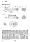
oI oD l MM AL A H GA GB L RR F K C CZ TT C TZ GA WA GB WB JW JH oe oIJ f ZZ + l + Stroke Z + l + Stroke 8 8 h + l 10° Wθ° Width across flats NA S + Stroke 2 x P (Rc, NPT, G) H1 ZZ + Stroke Z + Stroke Width across flats KA Width across flats B1 0 oE.0.05 R0.4 oCDH10 (Hole dia.) d9 (Shaft dia.) 8 x J Cushion valve, Width across flats WH 2 x P (Rc, NPT, G) Clevis: CG1DN (o20 to o63) With air cushion With rod boot * The minimum stroke with rod boot is 20 mm. With Air Cushion (mm) With Rod Boot (mm) * Refer to the basic type for the female rod end. Note) ( ): Denotes the dimensions for long stroke. (mm) (mm) Bore size Rc, NPT, G GA GB P WA WB Wθ WH 20 12 10 (12) M5 x 0.8 16 15 (16) 25° 1.5 25 12.5 10 (12.5) M5 x 0.8 16 14.5 (16) 25° 1.5 32 12 10 (12) 1/8 16 14 (16) 25° 1.5 40 13 10 (13) 1/8 17 15 (17) 20° 1.5 50 14 12 (14) 1/4 18 16 (18) 20° 3 63 14 12 (14) 1/4 18 17 (18) 20° 3 Bore size e f h IJ JH (Reference) JW (Reference) l Z ZZ 20 30 18 55 27 15.5 10.5 1/4 stroke 138 (146) 149 (157) 25 30 19 62 32 16.5 10.5 147 (155) 160 (168) 32 35 19 62 38 18.5 10.5 153 (161) 168 (176) 40 35 19 70 48 21.5 10.5 170 (179) 188 (197) 50 40 19 78 59 24 10.5 193 (205) 213 (225) 63 40 20 78 72 24 10.5 198 (210) 220 (232) Bore size Stroke range Rc, NPT port G port A AL B1 C CD CZ D E F H H1 I J K KA L MM NA Standard Long stroke GA GB P GA GB P 20 Up to 200 201 to 1500 12 10 (12) 1/8 12 10 (12) M5 x 0.8 18 15.5 13 14 8 29 8 12 2 35 5 26 M4 x 0.7 5 6 14 M8 x 1.25 24 25 Up to 300 301 to 1500 12 10 (12) 1/8 12.5 10 (12.5) M5 x 0.8 22 19.5 17 16.5 10 33 10 14 2 40 6 31 M5 x 0.8 5.5 8 16 M10 x 1.25 29 32 Up to 300 301 to 1500 12 10 (12) 1/8 10.5 10 (10.5) 1/8 22 19.5 17 20 12 40 12 18 2 40 6 38 M5 x 0.8 5.5 10 20 M10 x 1.25 35.5 40 Up to 300 301 to 1500 13 10 (13) 1/8 13 10 (10) 1/8 30 27 19 26 14 49 16 25 2 50 8 47 M6 x 1 6 14 22 M14 x 1.5 44 50 Up to 300 301 to 1500 14 12 (14) 1/4 14 12 (14) 1/4 35 32 27 32 16 60 20 30 2 58 11 58 M8 x 1.25 7 18 25 M18 x 1.5 55 63 Up to 300 301 to 1500 14 12 (14) 1/4 14 12 (14) 1/4 35 32 27 38 18 74 20 32 2 58 11 72 M10 x 1.5 7 18 30 M18 x 1.5 69 Bore size RR S TT TZ Z ZZ Applicable pin part no. 20 11 69 (77) 3.2 43.4 118 (126) 129 (137) CD-G02 25 13 69 (77) 3.2 48 125 (133) 138 (146) CD-G25 32 15 71 (79) 4.5 59.4 131 (139) 146 (154) CD-G03 40 18 78 (87) 4.5 71.4 150 (159) 168 (177) CD-G04 50 20 90 (102) 6 86 173 (185) 193 (205) CD-G05 63 22 90 (102) 8 105.4 178 (190) 200 (212) CD-G06 19 Series CG1