es20-224-cg1 67 / 96
10秒後にBOOKのページに移動します
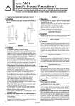
W W Caution Caution Use the Recommended Pneumatic Circuit Handling Series CBG1 Specific Product Precautions 1 Be sure to read this before handling. Refer to the back cover for Safety Instructions. For Actuator and Auto Switch Precautions, refer to “Handling Precautions for SMC Products” and the Operation Manual on SMC website, http://www.smcworld.com Head end lock Rod end lock . This is necessary for proper operation and release of the lock. 1. Do not use 3 position solenoid valves. Avoid use in combination with 3 position solenoid valves (especially closed center metal seal types). If pressure is trapped in the port on the lock mechanism side, the cylinder cannot be locked. Furthermore, even after being locked, the lock may be released after some time, due to air leaking from the solenoid valve and entering the cylinder. 2. Back pressure is required when releasing the lock. Be sure air is supplied to the side of the cylinder without a lock mechanism, (side of the piston rod without lock for double end lock), before starting up, as in the above figures. Otherwise, the lock may not be released. (Refer to “Releasing the Lock”.) 3. Release the lock when mounting or adjusting the cylinder. If mounting or other work is performed when the cylinder is locked, the lock unit may be damaged. 4. Operate with a load ratio of 50% or less. If the load ratio exceeds 50%, this may cause problems such as failure of the lock to release, or damage to the lock unit. 5. Do not operate multiple cylinders in synchronization. Avoid applications in which two or more cylinders with end lock are synchronized to move one workpiece, as one of the cylinder locks may not be able to release when required. 6. Use a speed controller with meter-out control. Lock cannot be released occasionally by meter-in control. 7. Be sure to operate completely to the cylinder stroke end on the side with the lock. If the cylinder piston does not reach the end of the stroke, locking and unlocking may not be possible. 8. Do not use the air cylinder as an air-hydro cylinder. This may result in oil leak. 9. Install a rod boot without twisting. If the cylinder is installed with its bellows twisted, it could damage the bellows. 10. Adjust an auto switch position so that it operates for movement to both the stroke end and backlash (2 mm) positions. When a 2-color indication switch is adjusted for green indication at the stroke end, it may change to red for the backlash return, but this is not abnormal. Warning Handling 1. Do not operate the cushion valve in the fully closed or fully opened state. Using it in the fully closed state will cause the cushion seal to be damaged. Using it in the fully opened state will cause the piston rod assembly or the cover to be damaged. 2. Operate within the specified cylinder speed. Otherwise, cylinder and seal damage may occur. Caution Operating Pressure 1. Supply air pressure of 0.15 MPa or higher to the port on the lock mechanism side, as it is necessary for releasing the lock. Caution Exhaust Speed 1. The lock will be engaged automatically if the pressure applied to the port on the lock mechanism side falls to 0.05 MPa or less. In cases where the piping on the lock mechanism side is long and thin, or the speed controller is separated at some distance from the cylinder port, the exhaust speed will be reduced. Take note that some time may be required for the lock to engage. In addition, clogging of a silencer mounted on the solenoid valve exhaust port can produce the same effect. Caution Relation to Cushion 1. When cushion valve at lock mechanism side is fully opened or closed, piston rod may not be reached at stroke end. Thus, lock is not established. And when locking is done at cushion valve fully closed, adjust cushion valve since lock may not be released. Warning Releasing the Lock 1. Before releasing the lock, be sure to supply air to the side without a lock mechanism, so that there is no load applied to the lock mechanism when it is released. (Refer to the recommended pneumatic circuits.) If the lock is released when the port on the other side is in an exhaust state, and with a load applied to the lock unit, the lock unit may be subjected to an excessive force and be damaged. Furthermore, sudden movement of the piston rod is very dangerous. Caution Disassembly/Replacement 1. Do not replace the bushings. The bushings are press-fit. To replace them, they must be replaced together with the cover assembly. 2. To replace a seal, apply grease to the new seal before installing it. If the cylinder is put into operation without applying grease to the seal, it could cause the seal to wear significantly, leading to premature air leakage. 3. Cylinders with o50 or larger bore sizes cannot be disassembled. When disassembling cylinders with bore sizes of o20 through o40, grip the double flat part of either the tube cover or the rod cover with a vise and loosen the other side with a wrench or a monkey wrench etc., and then remove the cover. When re-tightening, tighten approximately 2 degrees more than the original position. (Cylinders with o50 or larger bore sizes are tightened with a large tightening torque and cannot be disassembled. If disassembly is required, please contact SMC.) 65