es20-224-cg1 68 / 96
10秒後にBOOKのページに移動します
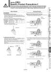
Lock piston Piston rod Spring Pressure . Pressure Back pressure Exhaust Exhaust Rubber cap Release Lock Caution Locked state Manual Release 1. Non-locking type manual release Insert the accessory bolt from the top of the rubber cap (it is not necessary to remove the rubber cap), and after screwing it into the lock piston, pull it to release the lock. If you stop pulling the bolt, the lock will return to an operational state. Thread sizes, pulling forces and strokes are as shown below. 2. Locking type manual release While pushing the M/O knob, turn it 90° counterclockwise. The lock is released (and remains in a released state) by aligning the mark on the cap with the OFF mark on the M/O knob. When locking is desired, turn the M/O knob 90° clockwise while pushing completely down, and align the mark on the cap with the ON mark on the M/O knob. The correct position is confirmed by a clicking sound. Failure to click it into place properly can cause the lock to disengage. Working Principle PHead end lock (Rod end lock is the same.) 1. When the piston rod is getting closer to the stroke end, the taper part (*) of the piston rod edge will push the lock piston up. 2. The lock piston is pushed up further. 3. The lock piston is pushed up into the groove of the piston rod to lock it. (The lock piston is pushed up by spring force.) At this time, it is exhausted from the port on the head side and introduced into the atmosphere. 4. When pressure is supplied in the head side, lock piston will be pushed up to release the lock. 5. When the lock is released, the cylinder will move forward. * The figures below are the same as those for Series CBA2. Remove the bolt for normal operation. It can cause lock malfunction or faulty release. Locked state Unlocked state Series CBG1 Specific Product Precautions 2 Be sure to read this before handling. Refer to the back cover for Safety Instructions. For Actuator and Auto Switch Precautions, refer to “Handling Precautions for SMC Products” and the Operation Manual on SMC website, http://www.smcworld.com Unlocked state Bore size (mm) Thread size Pulling force Stroke (mm) 20, 25, 32 M2.5 x 0.45 x 25 L or more 4.9 N 2 40, 50, 63 M3 x 0.5 x 30 L or more 10 N 3 80, 100 M5 x 0.8 x 40 L or more 24.5 N 3 66 CG1Q CBG1 CG1KR CG1R CG1KW CG1K CG1 CG1W CG1 Low Friction With End Lock Direct Mount, Non-rotating Rod Direct Mount Non-rotating Rod Standard Double Acting, Single Rod Double Acting, Single Rod Double Acting, Double Rod Double Acting, Single Rod Single Acting, Spring Return/Extend Double Acting, Double Rod Double Acting, Single Rod Made to Order Auto Switch