es20-224-cg1 85 / 96
10秒後にBOOKのページに移動します
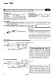
MK H2 ML + Adjustment oMI ZZ + 2 x Stroke + Adjustment (A: 25 mm, B: 50 mm) MH + Stroke + Adjustment MT Stroke S + Stroke Stopper bracket Width across flats B2 Stopper MM2 Width across flats MA MK H2 ML + Adjustment ZZ + 2 x Stroke + Adjustment (A: 25 mm, B: 50 mm) MH + Stroke + Adjustment oMI MT Stroke S + Stroke MM2 Width across flats B2 Width across flats MA Stroke adjustment mechanism -XC8 Symbol 7 Adjustable Stroke Cylinder/Adjustable Extension Type It adjusts the extending stroke by the stroke adjustable mechanism equipped in the head side. Specifications Stroke adjustment symbol A B Stroke adjustment range (mm) 0 to 25 0 to 50 Additional specifications Same as standard type Series CG1K/CG1R/CG1KR Bore size B2 H2 MA MH MI MK ML MM2 MT S ZZ 20 10 3.6 12 38 14 7 18 M6 x 1 9 83 148 25 13 5 17 41 20 9 18 M8 x 1.25 11 85 158 32 13 5 17 41 20 9 18 M8 x 1.25 11 91 164 40 17 6 19 47 25 10 24 M10 x 1.25 11 103 189 50 19 8 24 60 32 13 32 M14 x 1.5 11 120 225 63 19 8 24 60 32 13 32 M14 x 1.5 13 126 231 (mm) Precautions 1. When the cylinder is operating, if something gets caught between the stopper bracket for adjusting the stroke and the cylinder body, it could cause bodily injury or damage the peripheral equipment. Therefore, take preventive measures as necessary, such as installing a protective cover. 2. To adjust the stroke, make sure to secure the wrench flats of the stopper bracket by a wrench etc. before loosening the lock nut. If the lock nut is loosened without securing the stopper bracket, be aware that the area that joins the load to the piston rod or the area in which the piston rod is joined with the load side and the stopper bracket side could loosen first. It may cause an accident or malfunction. Warning Series CG1 * On the axial foot type, the foot is wedged and bolted between the cylinder and the stopper bracket at the time of shipment. On other types, it is placed in the same package, (but not assembled). (mm) Bore size B2 H2 MA MH MI MK ML MM2 MT S ZZ 20 10 3.6 12 38 14 7 18 M6 x 1 9 77 150 25 13 5 17 41 20 9 18 M8 x 1.25 11 77 158 32 13 5 17 41 20 9 18 M8 x 1.25 11 79 160 40 17 6 19 47 25 10 24 M10 x 1.25 11 87 184 50 19 8 24 60 32 13 32 M14 x 1.5 11 102 220 63 19 8 24 60 32 13 32 M14 x 1.5 13 102 220 Dimensions (Dimensions other than below are the same as standard type.) Applicable Series Description Model Action Note Standard type CG1 Double acting Non-rotating rod type CG1K Double acting Except with air cushion Direct mount type CG1R Double acting Except with air cushion Direct mount, Non-rotating rod type CG1KR Double acting Except with air cushion*1 *1 The shape is the same as the existing product. Use the existing seal kit. CG1KR How to Order Adjustable stroke cylinder/Adjustable extension type CG1 Mounting style Type Bore size Stroke Stroke adjustment symbol Z Pivot bracket Rod end bracket XC8 Mounting style Type Bore size Stroke Stroke adjustment symbol XC8 . Except head flange and clevis types 83 Series CG1