es20-224-cg1 90 / 96
10秒後にBOOKのページに移動します
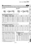
. Hs A B . Hs A B Auto Switch Proper Mounting Position/Applicable Cylinder Series: CDBG1-XC13 Note 1) For cylinders with end lock, add the above values to those listed in the table for CG1-XC13. Note 2) For the head and double end lock, add the above values to CG1-XC13 (long stroke) to find B. Note 3) Adjust the auto switch after confirming the operating condition in the actual setting. Note 4) For the dimensions other than the auto switch proper mounting position and its mounting height, refer to the standard type of the CBG1 series. (mm) Lock position Bore size H (Head end) R (Rod end) W (Double end) A B Note 2) A B A B Note 2) 20 +0 +12 +11 +0 +11 +12 25 +0.5 +11.5 +11.5 .0.5 +11.5 +11.5 32 +0 +10 +10 +0 +10 +10 40 +0 +14 +9 +0 +9 +14 50 +0 +17 +12 +0 +12 +17 63 +1.5 +15.5 +13.5 .1.5 +13.5 +15.5 80 .1.5 +23.5 +14.5 +1.5 +14.5 +23.5 100 .0.5 +23.5 +15.5 +0.5 +15.5 +22.5 Auto Switch Proper Mounting Position (Detection at stroke end) Applicable Cylinder Series: CDG1-XC13 (mm) Auto switch model Bore size D-M9l/D-M9lV D-M9lW/D-M9lWV D-M9lA/D-M9lAV D-F7l/F79F/F7lV D-J79/J79C D-F7lW/J79W/F7lWV D-F7NT D-A7l D-A80 D-A79W A B A B A B A B A B 20 31.5 22.5 (30.5) 30.5 21.5 (29.5) 35.5 26.5 (34.5) 30 21 (29) 27.5 18.5 (26.5) 25 31 23 (31) 30 22 (30) 35 27 (35) 29.5 21.5 (29.5) 27 19 (27) 32 32.5 23.5 (31.5) 31.5 22.5 (30.5) 36.5 27.5 (35.5) 31 22 (30) 28.5 19.5 (27.5) 40 37.5 25.5 (34.5) 36.5 24.5 (33.5) 41.5 29.5 (38.5) 36 24 (33) 33.5 21.5 (30.5) 50 44.5 30.5 (42.5) 43.5 29.5 (41.5) 49 34.5 (46.5) 43 29 (41) 40.5 26.5 (38.5) 63 43 32 (44) 42 31 (43) 47 36 (48) 41.5 30.5 (42.5) 39 28 (40) 80 56 37 (51) 55 36 (50) 60 41 (55) 54.5 35.5 (49.5) 52 33 (47) 100 55 38 (52) 54 37 (51) 59 42 (56) 53.5 36.5 (50.5) 51 34 (48) Note 1) ( ): For long stroke Note 2) Adjust the auto switch after confirming the operating condition in the actual setting. Auto Switch Proper Mounting Position (Detection at stroke end) Applicable Cylinder Series: CDG1R-XC13 (mm) Auto switch model Bore size D-M9l/D-M9lV D-M9lW/D-M9lWV D-M9lA/D-M9lAV D-F7l/F79F/F7lV D-J79/J79C D-F7lW/J79W/F7lWV D-F7NT D-A7l D-A80 D-A79W A B A B A B A B A B 20 10.5 22.5 9.5 21.5 14.5 26.5 9 21 6.5 18.5 25 10 23 9 22 14 27 8.5 21.5 6 19 32 11.5 23.5 10.5 22.5 15.5 27.5 10 22 7.5 19.5 40 16.5 25.5 15.5 24.5 20.5 29.5 15 24 12.5 21.5 50 18.5 30.5 17.5 29.5 22.5 34.5 17 29 14.5 26.5 63 17 32 16 31 21 36 15.5 30.5 13 28 Note) Adjust the auto switch after confirming the operating condition in the actual setting. D-F7BA/F7ABV D-A72/A7lH/A80H D-A73C/A80C D-F7BA/F7ABV D-A72/A7lH/A80H D-A73C/A80C -XC13 Symbol 12 Auto Switch Rail Mounting Auto Switch Mounting Height (mm) Series CDG1R (o20 to o63) Series CDG1 Auto switch model Bore size D-M9l/M9lV D-M9lW/M9lWV D-M9lA/M9lAV D-F7l/F79F D-J79/F7NT D-F7lW/J79W/F7BA D-F7lV D-F7lWV D-F7BAV D-J79C D-A7l D-A80 D-A73C D-A80C D-A79W Hs Hs Hs Hs Hs Hs 20 26.5 29 32 25.5 32.5 28 25 29 31.5 34.5 28 35 30.5 32 32.5 35 38 31.5 38.5 34 40 36.5 39 42 35.5 42.5 38 50 42 44.5 47.5 41 48 43.5 63 49 51.5 54.5 48 55 50.5 80 59 61.5 64.5 58 65 60.5 100 69.5 72 75 68.5 75.5 71 Auto Switch Proper Mounting Position (Detection at Stroke End) and Its Mounting Height 88 Made to Order Series CG1 CG1Q CBG1 CG1KR CG1R CG1KW CG1K CG1 CG1W CG1 Low Friction With End Lock Direct Mount, Non-rotating Rod Direct Mount Non-rotating Rod Standard Double Acting, Single Rod Double Acting, Single Rod Double Acting, Double Rod Double Acting, Single Rod Single Acting, Spring Return/Extend Double Acting, Double Rod Double Acting, Single Rod Made to Order Auto Switch