p-e13-12-arc 102 / 143
10秒後にBOOKのページに移動します
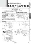
How to Order Air Inert gas 0.25 to 0.7 MPa .100 kPa to 0.7 MPa 24 VDC 0.45 W ±10% of rated voltage Fluid Rated voltage Power consumption Allowable voltage fluctuation SY7140-5DOS-X316-Q SY5140R-5DOS-Q SY7140-5DOS-X316-Q SY5140R-5DOS-Q SS5Y7-X424-Q 2 3 1 4 (M12 connector) Pneumatic circuit GAS AIR AIR GAS SS5Y7-X424-Q OUT AIR GAS 9.4 89.0 58.5 Approx. 560 60.5 13.0 77.7 Approx. 560 11.0 5.5 34.0 72.6 83.9 53.5 13.0 36.0 91.4 15.5 15.0 9.0 82.0 100.0 30.0 39.7 43.0 60.0 8.0 97.0 16.8 20.0 10.4 [Special specifications] 1. Special manifold air circuit. (Refer to the figure on the right.) 2. With special connector assembly (Cable: Glass fiber heat resistant cover) Note 1) Order no. “SS5Y7-X424-Q” includes the valve. Note 2) Since SY7140 is internal pilot type, be careful not to drop the supply pressure from the minimum operating pressure. X A A OUT (SY7140) Gas IN Air IN (SY5140R) X part no. CE marking SS5Y7 X424 Q Gas/Air Switching Valve Specifications Dimensions Operating pressure range Gas/Air switching valve With special connector assembly (Cable: Glass fiber heat resistant cover) X424 Flow-rate Characteristics (Cv Factor) AIR→OUT GAS→OUT SY7140 SY5140R 0.63 0.40 Passage Valve Cv Note 1) The flow-rate characteristics show the flow rates when this special base is mounted. Note 2) The flow rate is measured by means of the discharge method. Wiring M12 connector DIN connector . No polarity. Varistor 4 2 3 1 Coil (.) (+) (.) (+) Rc3/8 OUT port M12 connector 2 x M6 x 1 thread depth 8 (For mounting) M5 x 0.8 (PE port) Rc3/8 Air IN port Rc1/4 Gas IN port M12 connector 94 Clamp Cylinders Spatter Resistant Cylinders for Arc Welding Flow Control Equipment Fittings Tubing Detection Switches Gas/Air Switching Valve