p-e13-12-arc 107 / 143
10秒後にBOOKのページに移動します
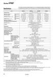
Note 1) When the minimum unit setting 0.01 L/min is selected for 10 L/min type, the indication upper limit will be [9.99 L/min]. When the minimum unit setting 0.1 L/min is selected for 100 L/min type, the indication upper limit will be [99.9 L/min]. Note 2) User can select between 0.01 L/min and 0.1 L/min for the PFM710, and between 0.1 L/min and 1 L/min for the PFM711 respectively. If the indication unit is selected to “CFM”, the minimum unit setting cannot be changed. At the time of shipment from the factory, the minimum unit setting is set to 0.1 L/min for the PFM710 and 1 L/min for the PFM711 respectively. Note 3) Set to “ANR” at the time of shipment from the factory. “ANR” is used for standard conditions: 20°C, 1 atm and 65%R.H. “NL/min” is used for normal conditions: 0°C and 1 atm. When equipped with a unit switching function. (The SI unit (L/min or L) is fixed for types with no unit switching function.) Note 4) Cleared when the power supply is turned off. Hold function can be selected. (Interval of 2 min or 5 min can be selected). If the 5 min interval is selected, the life of the memory element (electronic part) is limited to 1 million cycles. (If energized for 24 hours, life is calculated as 5 min x 1 million = 5 million min = 9.5 years). Therefore, if using the hold function, calculate the memory life for your operating conditions, and use within this life. Note 5) Set to 1.5 s (90%), can be changed to 100 ms. Note 6) Set to hysteresis mode at the time of shipment from the factory. Can be changed to window comparator mode using push-buttons. Note 7) For details about wiring and thread type, refer to the Operation Manual that can be downloaded from SMC website (http://www.smcworld.com). Note 8) When using argon (Ar), carbon dioxide (CO2) and the mixed gas (Ar + CO2), refer to page 101. Model PFM710 PFM725 PFM750 PFM711 Applicable fluid Pressure characteristics Repeatability Operating pressure range Rated pressure range Proof pressure Accumulated flow range Switch output Accumulated pulse output External input Display method Status LED’s Power supply voltage Current consumption Environment Indication unit Note 3) Minimum unit setting Note 2) Accumulated pulse flow rate exchange value Rated flow range Note 8) (Flow rate range) Dry air, N2, Ar CO2 Maximum load current Maximum applied voltage Internal voltage drop Response time Output protection Enclosure Operating fluid temperature Operating temperature range Operating humidity range Withstand voltage Insulation resistance Hysteresis mode Window comparator mode Response time Displayable range Note 1) Note 8) Settable range Note 1) Note 8) Dry air, N2, Ar CO2 Dry air, N2, Ar CO2 Dry air, N2, Ar, CO2 (Air quality grade is JIS B8392-1, 1.1.2 to 1.6.2 and ISO8573-1, 1.1.2 to 1.6.2.) 0.2 to 10 L/min 0.2 to 5 L/min 0.2 to 10.5 L/min 0.2 to 5.2 L/min 0 to 10.5 L/min 0 to 5.2 L/min 0.01 L/min 0.1 L/pulse 0.5 to 25 L/min 0.5 to 12.5 L/min 0.5 to 26.3 L/min 0.5 to 13.1 L/min 0 to 26.3 L/min 0 to 13.1 L/min 0.1 L/min 0.1 L/pulse Linearity Temperature characteristics Analog output Note 5) Note 8) Hysteresis Note 6) 1 to 50 L/min 1 to 25 L/min 1 to 52.5 L/min 1 to 26.2 L/min 0 to 52.5 L/min 0 to 26.2 L/min 0.1 L/min 0.1 L/pulse 2 to 100 L/min 2 to 50 L/min 2 to 105 L/min 2 to 52 L/min 0 to 105 L/min 0 to 52 L/min 0.1 L/min 1 L/pulse Voltage output Current output Series PFM7 Specifications ±1%F.S. (Fluid: Dry air) Analog output accuracy: ±3%F.S. (Fluid: Dry air) ±5%F.S. (0.35 MPa reference) .100 kPa to 750 kPa .70 kPa to 750 kPa 1 MPa Max. 999999 L Note 4) NPN or PNP open collector output 80 mA 28 VDC (at NPN output) NPN output: 1 V or less (at 80 mA) PNP output: 1.5 V or less (at 80 mA) 1 s (50 ms, 0.5 s, 2 s can be selected.) Short-circuit protection NPN or PNP open collector output (Same as switch output) 1.5 s or less (90% response) Variable Variable No-voltage input (Reed or Solid state) Input 30 ms or more 3-digit, 7-segment LED 2-color display (Red/Green) Renewed cycle: 10 times/sec OUT1: Lights up when output is turned ON (Green). OUT2: Lights up when output is turned ON (Red). 24 VDC ±10% 55 mA or less IP40 0 to 50°C (with no freezing and condensation) Operating: 0 to 50°C Stored: .10 to 60°C (with no freezing and condensation) Operating, Stored: 35 to 85%R.H. (with no condensation) 1000 VAC for 1 minute between terminals and housing 50 MΩ or more (500 VDC measured via megohmmeter) between terminals and housing Instantaneous flow rate L/min, CFM x 10-2 Accumulated flow L, ft3 x 10-1 ±2%F.S. (15 to 35°C) ±5%F.S. (0 to 50°C) Voltage output: 1 to 5 V Output impedance: 1 kΩ Current output: 4 to 20 mA Max. load impedance: 600 Ω, Min. load impedance: 50 Ω Display accuracy: ±3%F.S. (Fluid: Dry air) Analog output accuracy: ±5%F.S. (Fluid: Dry air) For details about the Flow Switch Precautions, refer to “Handling Precautions for SMC Products”. For details about the Specific Product Precautions, refer to the Operation Manual at SMC website. 99