p-e13-12-arcБ@Б@Б@14 / 143
10ХbМуВ╔BOOKВ╠ГyБ[ГWВ╔И┌УоВ╡В▄В╖
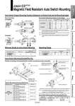
Auto Switch Proper Mounting Position (Detection at Stroke End) and Its Mounting Height Note 1) The mounting position should be referred for reference only for the auto switch mounting position at the stroke end detection. Adjust the auto switch after confirming the operation to set actually. Note 2) A/B dimensions are the distance from the standard position (above drawing) to the end surface of the auto switch. Note 3) The auto switch mounting position is temporarily set at the time of shipping from our factory. Change it to the desired position in accordance to your facility. Auto Switch Mounting Position and Its Height Unit: mm Auto switch model D-P3DWAЁо D-P4DWЁо Symbol AB Hs Auto switch set value and its height o63 7 30 59 o50 7 30 52 o40 9.5 24.5 46.5 AB Hs 4.5 27.5 58.5 4.5 27.5 51 8 20.5 45.5 Minimum Stroke for Auto Switch Mounting Unit: mm Auto switch model D-P3DWAЁо D-P4DWЁо With 1 pc. 50 50 Different surfaces Same surface With 2 pcs. Unit: mm Auto switch model 5.5 4 5.5 4 5.5 4.5 Bore size D-P3DWAЁо D-P4DWЁо 40 50 63 Operating Range Note) When two D-P3DWЁн are mounted to the cylinder with stroke 50 mm, mount them on different surfaces. Rod mounting D-P3DWAЁо Different surfaces Same surface Magnetic Field Resistant Auto Switch Mounting A B .Hs CKG1-XC88/XC89 -XC91 Auto Switch Mounting Bracket/Part No. Switch Mounting Rod Assembly/Part No. CKG40-R050 CKG40-R075 CKG40-R100 CKG40-R125 CKG40-R150 Applicable series Applicable clamp cylinder Part no. CKG1Ён40-150 CKG1Ён50-150/CKP1Ён50-150 CKG1Ён63-150/CKP1Ён63-150 CKG1Ён40-50 CKG1Ён50-50/CKP1Ён50-50 CKG1Ён63-50/CKP1Ён63-50 CKG1Ён40-75 CKG1Ён50-75/CKP1Ён50-75 CKG1Ён63-75/CKP1Ён63-75 CKG1Ён40-100 CKG1Ён50-100/CKP1Ён50-100 CKG1Ён63-100/CKP1Ён63-100 CKG1Ён40-125 CKG1Ён50-125/CKP1Ён50-125 CKG1Ён63-125/CKP1Ён63-125 Series CKG1Ёо40/50/ 63 Auto Switch Mounting Bracket Assembly/Part No. Applicable cylinder series Applicable auto switch model Auto switch mounting bracket part no. 40 50 63 Series CKG1 D-P3DWAЁн BK7-040S D-P4DWЁн BK1T-040 Switch mounting rod assembly/Auto switch mounting bracket assembly Switch mounting rod assembly Collar Switch mounting rod Hexagon socket head button bolt (M4 tightening torque: 1.0 to 1.2 NБEm) D-P4DWЁо A 32 4 B .Hs . Mount the part E of the auto switch mounting bracket so that it is in contact with the cylinder tube. Note 1) The tightening torque for a hexagon socket head cap screw (M2.5) is 0.2 to 0.3 NБEm. Hold the shorter side of a hexagon wrench, and turn it to tighten. (Too much tightening may break the switch) Note 2) Tighten the hexagon socket head cap screws B and C (M4) with a tightening torque of 1 to 1.2 NБEm. Switch mounting rod Auto switch mounting bracket B E . Auto switch mounting bracket (Attached to auto switch) Hexagon socket head cap screw A (M2.5 x 11L) Hexagon socket head cap screw C (M4 x 5L) Auto switch Hexagon socket head cap screw B (M4 x 8L) 12 Clamp Cylinders Spatter Resistant Cylinders for Arc Welding Flow Control Equipment Fittings Tubing Detection Switches Gas/Air Switching Valve A