p-e13-12-arc 20 / 143
10秒後にBOOKのページに移動します
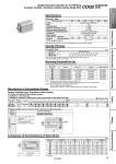
Comparison of the Dimensions of Each Series L B + Stroke A + Stroke Specifications 32 40 50 63 80 100 0.15 0.29 0.26 0.52 Double acting, Single rod Air 1.5 MPa 1.0 MPa 0.05 MPa .10 to 60°C (No freezing) Not required (Non-lube) 50 to 500 mm/s 0.46 0.91 0.77 1.54 1.36 2.71 2.27 4.54 Action Fluid Proof pressure Maximum operating pressure Minimum operating pressure Ambient and fluid temperature Lubrication Piston speed Stroke length tolerance Standard With rubber bumper Bore size (mm) Note) Stroke length tolerance does not include the amount of bumper change. Allowable kinetic energy (J) +1.0 mm Note) 0 Pneumatic type Standard Strokes 32, 40 50 to 100 5, 10, 15, 20, 25, 30, 35, 40, 45, 50, 75, 100 10, 15, 20, 25, 30, 35, 40, 45, 50, 75, 100 . For long strokes exceeding the standard stroke range, refer to page 27. . For intermediate strokes, refer below. Bore size Standard stroke Pneumatic type (mm) Manufacture of Intermediate Strokes Spacer-installed type: Standard model number 32 40 50 63 80 100 CQ-L032-XC35 CQ-L040 CQ-L050 CQ-L063 CQ-L080 CQ-L100 CDQ2尰尰-尰DZ CDQ2尰尰-尰DZ CDQ2尰尰-尰DZ CDQ2尰尰-尰DZ CDQ2尰尰-尰DZ CDQ2尰尰-尰DZ CQ-F032-XC35 CQ-F040 CQ-F050 CQ-F063 CQ-F080 CQ-F100 CQ-D032 CQ-D040 CQ-D050 CQ-D063 CQ-D080 CQ-D100 Bore size (mm) Model Foot Note 1) Flange Double clevis Mounting Brackets/Part No. Note 1) Order two foot brackets per cylinder. (except o32) For o32 type, order 1 piece per cylinder. (Part number for a set of 2 foot brackets) Note 2) Parts belonging to each bracket are as follows. Foot or Flange: Body mounting bolts Double clevis: Clevis pin, Type C retaining rings for axis, Body mounting bolts . At 0 stroke Bore size (mm) Standard (mm) 32 40 50 63 80 100 XC88, 89 XC91 A 50 56.5 58.5 64 73.5 85 A 45 51.5 53.5 59 68.5 80 B 33 39.5 40.5 46 53.5 63 L 17 17 18 18 20 22 B 33 39.5 40.5 46 53.5 63 L 12 12 13 13 15 17 A 40 46.5 48.5 54 63.5 75 B 33 39.5 40.5 46 53.5 63 XC35 A 45 51.5 53.5 59 68.5 80 B 33 39.5 40.5 46 53.5 63 L 7 7 8 8 10 12 L 12 12 13 13 15 17 Spacer-installed type 1 !A spacer is installed on the standard strokes. !Available in 1 mm intervals !A spacer is installed on tubes with a stroke longer than the specified stroke ( ). 32, 40 50 to 100 CDQ2B32-57DZ-XC89 5 10 15 20 25 30 35 40 45 50 75 100 B Spacer Bore size (mm) Stroke Stroke range Type : Standard stroke 1 to 99 1 to 99 Ordering example: o32-57 mm stroke, with through-hole and without auto switch Type Part no. Order no. Description Spacer-installed type 1 Standard model number !Uses a standard stroke (75 mm) tube. !Makes 57 mm stroke with 18 mm spacer inside. !The B dimension is 108 mm. Ordering example CDQ2-XC88/XC89 -XC91 Spatter Resistant Cylinder for Arc Welding Compact Cylinder: Standard, Double Acting, Single Rod 18 Clamp Cylinders Spatter Resistant Cylinders for Arc Welding Flow Control Equipment Fittings Tubing Detection Switches Gas/Air Switching Valve