p-e13-12-arc 21 / 143
10秒後にBOOKのページに移動します
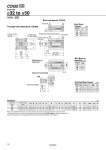
Z H1 R R M E J W oD Q F L E M K 2 oTh9 C1 X L1 MM oTh9 10 B + Stroke A + Stroke Minimum lead wire bending radius 10 Auto switch 2 x P (Rc, NPT, G) (Port size) O1 thread 4 x oN through 8 x oO counterbore H thread effective depth C Width across flat B1 Bore Size o32 to o50 Standard (mm) Note 1) The external dimensions with rubber bumper are same as those of the standard, as shown above. . For details about the rod end nut and accessory brackets, refer to the WEB catalog or Best Pneumatics No.2. Note 2) For calculation on the longitudinal dimension of intermediate strokes, refer to page 18. Through-hole (Standard): CDQ2B Rod end male thread With boss on head end Both ends tapped: CDQ2A R 10 10 14 Both Ends Tapped Bore size (mm) 32 40 50 O1 M6 x 1.0 M6 x 1.0 M8 x 1.25 (mm) (mm) With Boss on Head End Bore size (mm) 32 40 50 Th9 21 0 .0.052 28 0 .0.052 35 0 .0.062 32 40 50 C1 20.5 20.5 26 H1 8 8 11 B1 22 22 27 L1 38.5 38.5 43.5 MM M14 x 1.5 M14 x 1.5 M18 x 1.5 X 23.5 23.5 28.5 Rod End Male Thread Bore size (mm) (mm) CDQ2-XC88 -XC89 Bore size (mm) 32 40 50 Stroke range (mm) 5 to 50, 75, 100 5 to 50, 75, 100 10 to 50, 75, 100 A 50 56.5 58.5 B 33 39.5 40.5 C 13 13 15 D 16 16 20 E 45 52 64 J 4.5 5 7 H M8 x 1.25 M8 x 1.25 M10 x 1.5 Q 10 12.5 10.5 F 7.5 7.5 10.5 P 1/8 1/8 1/4 K 14 14 17 L 17 17 18 M 34 40 50 N 5.5 5.5 6.6 O 9 depth 7 9 depth 7 11 depth 8 W 49.5 57 71 Th9 Z 14 15 19 23 0 .0.052 28 0 .0.052 35 0 .0.062 CDQ2-XC88 -XC89 19