p-e13-12-arc 26 / 143
10秒後にBOOKのページに移動します
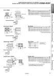
L1 L1 L1 FT L B + Stroke A + Stroke M FV FX FZ CX CZ CT CU L B + Stroke CW RR CL + Stroke A + Stroke FT A + Stroke L B + Stroke M FV FX FZ 4 x oFD 4 x N Cap bolt oCD hole H10 Axis d9 4 x oFD .0.1 .0.3 +0.4 +0.2 4 x oLD LZ LX LY LH Special cap bolt L B + Stroke A + Stroke LS + Stroke X Y Y X LT LG T T oI oI L1 Foot: CDQ2L Rod flange: CDQ2F Rod end male thread Head flange: CDQ2G Double clevis: CDQ2D Rod end male thread Rod end male thread Rod end male thread Foot (mm) Bore size (mm) 32 40 50 A 52.2 58.7 61.7 B 33 39.5 40.5 LS 17 23.5 17.5 L 12 12 13 L1 38.5 38.5 43.5 LD 6.6 6.6 9 LG 4 4 5 LH 30 33 39 LT 3.2 3.2 3.2 LX 57 64 79 LY 57 64 78 Rod Flange (mm) Bore size (mm) 32 40 50 A 45 51.5 53.5 B 33 39.5 40.5 FD 5.5 5.5 6.6 FT 8 8 9 FV 48 54 67 FX 56 62 76 FZ 65 72 89 L 12 12 13 L1 38.5 38.5 43.5 M 34 40 50 I 23 28 35 T 2 2 1 Head Flange (mm) Bore size (mm) 32 40 50 A 53 59.5 62.5 . For details about the rod end nut and accessory brackets, refer to the WEB catalog or Best Pneumatics No. 2. . A double clevis pin and retaining rings are included. Double Clevis (mm) Bore size (mm) 32 40 50 A 75 83.5 95.5 B 33 39.5 40.5 CL 65 73.5 81.5 CD 10 10 14 CT 5 6 7 CU 14 14 20 CW 20 22 28 CX 18 18 22 CZ 36 36 44 L 12 12 13 L1 38.5 38.5 43.5 LZ 71 78 95 X 11.2 11.2 14.7 Y 5.8 7 8 N M6 x 1.0 M6 x 1.0 M8 x 1.25 RR 10 10 14 Foot bracket material: Carbon steel Surface treatment: Nickel plating Flange bracket material: Carbon steel Surface treatment: Nickel plating Flange bracket material: Carbon steel Surface treatment: Nickel plating Double clevis bracket material: Cast iron Surface treatment: Painted . The dimensions except A are the same as those of the rod flange. CDQ2-XC91 Spatter Resistant Cylinder for Arc Welding Compact Cylinder: Standard, Double Acting, Single Rod 24 Clamp Cylinders Spatter Resistant Cylinders for Arc Welding Flow Control Equipment Fittings Tubing Detection Switches Gas/Air Switching Valve