p-e13-12-arc 31 / 143
10秒後にBOOKのページに移動します
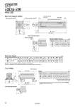
H1 C1 X L1 Q Q oTh9 10 oD L MM K M E W J E M Z X Y X Y LT L LG LZ LX LY LH L1 B + Stroke A + Stroke Width across flat B1 Minimum lead wire bending radius 10 Auto switch 2 x P (Rc, NPT, G) H thread effective depth C 8 x O thread effective depth R (Port size) Special cap bolt A + Stroke LS + Stroke B + Stroke 4 x oLD Foot: CDQ2L Bore Size o32 to o50 Rod end male thread Both ends tapped: CDQ2A Rod end male thread 32 40 50 22 22 27 B1 20.5 20.5 26 C1 8 8 11 H1 MM M14 x 1.5 M14 x 1.5 M18 x 1.5 L1 38.5 38.5 43.5 23.5 23.5 28.5 X 32 40 50 32 40 50 125 to 200 Note 1) 250, 300 A B C D E H J K L M O P Q R Th9 W M8 x 1.25 M8 x 1.25 M10 x 1.5 M6 x 1.0 M6 x 1.0 M8 x 1.25 10 12.5 14 10 10 14 49.5 57 71 Z 14 15 19 1/8 1/8 1/4 67.5 77 78.5 50.5 60 60.5 13 13 15 16 16 20 45 52 64 4.5 5 7 14 14 17 17 17 18 34 40 50 23 28 35 0 .0.052 0 .0.052 0 .0.062 Y 5.8 7 8 X 11.2 11.2 14.7 LZ 71 78 95 LY 57 64 78 LX 57 64 79 LT 3.2 3.2 3.2 LS 34.5 44 37.5 LH 30 33 39 LG 4 4 5 LD 6.6 6.6 9 L1 38.5 38.5 43.5 L 17 17 18 B 50.5 60 60.5 A 74.7 84.2 86.7 (mm) Both Ends Tapped (mm) (mm) Rod End Male Thread Bore size (mm) Bore size (mm) Stroke range (mm) Note 1) For 125 to 200 strokes, strokes are available in 25 mm intervals. Note 2) For calculation on the longitudinal dimension of intermediate strokes, refer to page 18. Foot . For details about the rod end nut and accessory brackets, refer to the WEB catalog or Best Pneumatics No.2. Bore size (mm) Foot bracket material: Carbon steel Surface treatment: Nickel plating CDQ2-XC88 -XC89 CDQ2-XC88 -XC89 29