p-e13-12-arcپ@پ@پ@36 / 143
10•bŒم‚ةBOOK‚جƒyپ[ƒW‚ةˆع“®‚µ‚ـ‚·
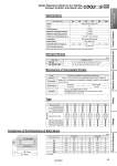
L Comparison of the Dimensions of Each Series 5, 10, 15, 20, 25, 30, 35, 40, 45, 50, 75, 100 10, 15, 20, 25, 30, 35, 40, 45, 50, 75, 100 32 40 50 63 80 100 0.29 0.52 0.91 1.54 2.71 4.54 32, 40 50, 63, 80, 100 (mm) Bore size Standard stroke Standard Strokes Action Fluid Proof pressure Maximum operating pressure Minimum operating pressure Ambient and fluid temperature Lubrication Piston speed Allowable kinetic energy (J) Stroke length tolerance Bore size (mm) Note) Stroke length tolerance does not include the amount of dumper change. Double acting, Single rod Air 1.5 MPa 1.0 MPa 0.05 MPa .10 to 60پ‹C (No freezing) Not required (Non-lube) 50 to 500 mm/s +1.0 mm 0 Note) Specifications Type Part no. Refer to پgHow to Orderپh for the standard model number. (Page 33) Part no.: CDQ2BS50-57DCZ-XC89 CDQ2BS50-75DCZ-XC89 with 18 mm width spacer inside The B dimension is 125.5 mm. Strokes in 1 mm intervals are available by installing a spacer in the standard stroke cylinder. Description Stroke range Bore size 32 to 100 Stroke range 1 to 99 Example A spacer is installed in the standard stroke body. Manufacture of Intermediate Strokes 32 40 50 63 80 100 ً— ً— ً— Rc1/8 NPT1/8 G1/8 ً— ً— ً— Through-hole (Standard) Both ends tapped Built-in magnet for auto switch Rod end male thread With rubber bumper (Standard) With boss on head end Piping Mounting Bore size (mm) ً— ً— ً— Rc1/8 NPT1/8 G1/8 ً— ً— ً— ً— ً— ً— Rc1/4 NPT1/4 G1/4 ً— ً— ً— ً— ً— ً— Rc1/4 NPT1/4 G1/4 ً— ً— ً— ً— ً— ً— Rc3/8 NPT3/8 G3/8 ً— ً— ً— ً— ً— ً— Rc3/8 NPT3/8 G3/8 ً— ً— ً— Pipe thread Type Pneumatic . At 0 stroke Bore size (mm) Standard (mm) 32 40 50 63 80 100 XC88, 89 A 60 66.5 68.5 74 83.5 95 B 43 49.5 50.5 56 63.5 73 L 17 17 18 18 20 22 A 50 56.5 58.5 64 73.5 85 B 43 49.5 50.5 56 63.5 73 L 17 17 18 18 20 22 A + Stroke B + Stroke CDQ2ًS-XC88 -XC89 Spatter Resistant Cylinder for Arc Welding Compact Cylinder: Anti-lateral Load 34 Clamp Cylinders Spatter Resistant Cylinders for Arc Welding Flow Control Equipment Fittings Tubing Detection Switches Gas/Air Switching Valve