p-e13-12-arcЃ@Ѓ@Ѓ@42 / 143
10•bЊг‚ЙBOOK‚МѓyЃ[ѓW‚Й€Ъ“®‚µ‚Ь‚·
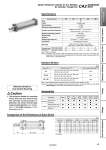
H S + Stroke Bore size Standard stroke Note 1) 25, 50, 75, 100, 125, 150, 175, 200, 250, 300, 350, 400, 450, 500 25, 50, 75, 100, 125, 150, 175, 200, 250, 300, 350, 400, 450, 500, 600 25, 50, 75, 100, 125, 150, 175, 200, 250, 300, 350, 400, 450, 500, 600, 700 40 50, 63 80, 100 (mm) Mounting Standard Option Rod end nut Clevis pin Single knuckle joint Basic р— . р— р— р— . р— р— р— . р— р— р— . р— р— р— р— р— р— р— . р— р— Double knuckle joint (With pin) Rod flange Axial foot р— . р— р— Head flange Single clevis Double clevis Center trunnion Minimum Stroke for Auto Switch Mounting 1. The minimum stroke for mounting varies with the auto switch type and cylinder mounting type. In particular, the center trunnion type needs careful attention. (For details, refer to the WEB catalog or Best Pneumatics No.2.) Caution Comparison of the Dimensions of Each Series Max. manufacturable stroke Note 2) 1000 1000 1000 Note 1) Intermediate strokes not listed above are produced upon receipt of order. Note 2) For details about applicable maximum stroke, refer to the model selection table (The WEB catalog or front matter 34 of the Best Pneumatics No.2). Fluid Action Proof pressure Maximum operating pressure Ambient and fluid temperature Minimum operating pressure Piston speed Cushion Stroke length tolerance Lubrication Mounting Allowable kinetic energy (J) Note 2) When air cushion is activated When air cushion is not activated Air Double acting 1.5 MPa 1.0 MPa Without auto switch: .10 to 70Ѓ‹C Note 1) With auto switch: .10 to 60Ѓ‹C Note 1) 0.05 MPa 50 to 500 mm/s Air cushion Not required (Non-lube) Basic, Foot, Rod flange, Head flange Single clevis, Double clevis, Center trunnion Bore size (mm) Specifications 40 50 63 80 100 0.33 0.56 0.91 1.50 2.68 2.8 4.6 7.8 16 29 Accessories Note 1) With no freezing Note 2) Activate the air cushion when operating the cylinder. If this is not done, the piston rod assembly or the tie-rods will be damaged when the allowable kinetic energy exceeds the values shown in the table above. Up to 250 st : +1.0 0 251 to 1000 st : +1.4 0 Standard Strokes . At 0 stroke Bore size (mm) Standard (mm) 40 50 63 80 100 XC88, 89 XC91 S 95 101 112 133 143 H 56 60 60 73 74 S 95 101 112 133 143 H 51 58 58 71 72 S 95 101 112 133 143 H 51 58 58 71 72 XC35 S 95 101 112 133 143 H 51 58 58 71 72 CA2-XC88/XC89 -XC91 Spatter Resistant Cylinder for Arc Welding Air Cylinder: Single Rod 40 Clamp Cylinders Spatter Resistant Cylinders for Arc Welding Flow Control Equipment Fittings Tubing Detection Switches Gas/Air Switching Valve