p-e13-12-arc 85 / 143
10秒後にBOOKのページに移動します
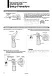
Workpiece contact mark Clamp arm Arrow Clamp end mark The clamp is engaging the workpiece. Workpiece Manually rotate the arm toward the clamp side. Workpiece contact mark Extension arm Clamp arm Clamping block Shim Arrow Clamp end mark The clamp is engaging the workpiece. Workpiece Manually rotate the arm toward the clamp side. Arrow Clamp end mark Air supply Shim Clamp arm Side guide Fulcrum Reference hole Clamp arm Shim Extension arm Lower surface of clamp arm Clamping block H±0.1 1. Since the distance accuracy from the reference hole to the lower surface of the clamp arm is ±0.1 mm at the stroke end as shown in the figure on the left side, a hard stop is not required on the clamping side. When a clamp arm deflection lock is required, install the side guides. 2. For clamping force adjustment, be sure to install a shim around 3 mm in size. 3. Even when the clamp arm operates to the clamp end, the internal toggle mechanism does not enter the dead point (2° short of the dead point). Therefore, clamping cannot be held during air exhaust. Step 1 Exhaust the air to switch to the unclamped state. Step 2 Manually place the arm on workpieces. Adjust with the shim so that the arrow is located between the workpiece contact mark and clamp end mark. Step 3 Supply air to the clamp side and adjust with the shim so that the arrow mark is located at a position close to the clamp end mark. Design and mounting Adjustment * In this cylinder, the shim is pulled out to increase the clamping force. Slim-line Power Clamp Cylinder CKZ2N-X2346 Setup Procedure Be sure to install a speed controller and adjust it so that it takes at least 1 second to clamp or unclamp. (Operating the cylinder in less than 1 second may cause damage to the product.) Caution 77