p-e13-12-arc 90 / 143
10秒後にBOOKのページに移動します
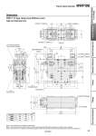
C B A±0.5 2 x M12 x 1.75 depth 24 15 4 x M8 x 1.25 depth 12 60 108 15 80 60±0.05 +0.015 2 x o8H7( 0 )de pth 12 (2 x 4 x M5 x 0.8 through) For limit switch mounting Rc1/ 4 Clamp side port 2 x 2 x o8H7 +0.015 ( 0 ) depth 12 2 x 4 x M10 x 1.5 depth 12 1 Switch mounting bracket Note 2) Rc1/ 4 Unclamp side port Limit switch Note 1) 60 52 12° 55 12° F Fulcrum 107 Note 3) 70 55 330 193 270 ±0.3 25 360 306 100 100 70±0.05 95 85 75 133 100±0.3 70 13 40 10 15 (173) (58.7) (70) (10) (30.2) (30.2) 139 4 x o14 through +0.015 4 x o8H7( 0 ) through 50 82±0.05 115 143 330±0.05 320 Arm type A B C T200 T240 T270 (mm) 200 240 270 340 360 380 29 19 9 Note 1) This product does not include the limit switch. Note 2) For mounting the limit switch, order the switch mounting bracket (WRF-BK) separately. For details, refer to page 86. Note 3) The symbol F in the dimensions indicates the position where the clamping force is generated defined by the product specifications. Dimensions WRF100-T200/T240/T270 WRF-T/T-type clamp arms (Without cover) Frame Clamp Cylinder WRF100 82 Clamp Cylinders Spatter Resistant Cylinders for Arc Welding Flow Control Equipment Fittings Tubing Detection Switches Gas/Air Switching Valve