m-03-3c-seihin_en 24 / 77
10秒後にBOOKのページに移動します
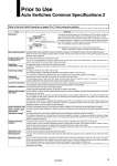
Prior to Use Auto Switches Common Specifications 2 Refer to the Auto Switch Precautions on pages 13 to 17 before using auto switches. A position (sensor layout position) where the sensitivity is highest on the detection surface of the auto switch enclosure. When the center of the magnet is aligned with this position, this becomes almost the center of the operating range and stable operation can be obtained. One of elements making up the sequence control. The PLC is so designed that it receives signals, such as auto switch output and outputs them to other devices so as to perform the electrical control according to the preset program. A temperature range, in which the auto switch can be used. If significant temperature change or freezing occurs even in this temperature range, this may cause the auto switch to malfunction. A voltage, at which the auto switch can be used. The operating voltage is indicated using generally used voltage (24 VDC or 100 VAC, etc.). For 2-wire type, the operating voltage has the same meaning as the power supply voltage or load voltage. A range of the current value that can be flowed to the output of the auto switch. If the operating current is lower than this range, the auto switch does not operate correctly. Conversely, if the operating current is higher than this range, this may cause the auto switch to break. This current value is necessary for the 3-wire type auto switch to operate the circuit through the power cable. For 2-wire type, as the current consumption is a part of the load current, it is not defined. A resistance between the electric circuit and enclosure. Unless otherwise described particularly, 50 MΩ (Min) is used for auto switch. An auto switch, for which measures against effects arising from external (welding) magnetic field generated in the spot welding process, etc. are taken. The solid state auto switch functions as it detects the frequency of the applied magnetic field. If the external magnetic field (AC) is applied, the last signal is retained not to be affected by the external magnetic field. This system can be used by the cylinder with normal magnetic force. The reed auto switch built-in a magnetic field shielded sensor with a low sensitivity to make the effect of the external magnetic field (DC or AC magnetic field) insusceptible. Therefore, a dedicated cylinder built-in the strong magnet needs to be selected and there is also an operable range (conditions). A minimum acceleration that may cause the auto switch to malfunction or break when the standard impact is applied. A model, long-term water resistance of which is improved by taking structural measures for the general (general purpose) product. A tolerance dose when the voltage is applied to the portion between the electrical circuit and enclosure. The withstand voltage shows a strength level of the product against the voltage. If a voltage exceeding the withstand voltage is applied, this may cause the product to break. (The voltage described here is different from the power supply voltage necessary to operate the product.) A dimension that shows the mounting position when the position is detected at the stroke end of the cylinder. As this position is set, the maximum sensitivity position is aligned with the center of the magnet. However, make the adjustment with the actual machine by considering the characteristic difference during actual setting. When an adjustment allowance is needed for the detection before the stroke, set a value with an adjustment allowance added to the proper mounting position. A device that is assumed as a target load of the auto switch. A period of time until the auto switch output becomes stable after the magnetic force to operate the auto switch has been received. An auto switch operating range in response to the cylinder piston movement (ON length in response to the stroke). The operating range is determined by the magnetic force of the magnet (range, in which the magnetic force acts) and switch sensitivity. So, the operating range may vary as these conditions are changed by the ambient environment, etc. The operating range in the standard status (normal temperature, single cylinder, magnetic force, and sensitivity, etc.) is described in the catalog. Note) Hysteresis may fluctuate due to the operating environment. Please contact SMC if hysteresis causes an operational problem. Term Meaning Hysteresis Auto switch Switch operating position (ON) Hysteresis Reed auto switch: 2 mm or less Solid state auto switch: 1 mm or less Switch operating position (OFF) Most sensitive position Programmable Logic Controller (PLC) Operating temperature range Operating voltage Operating current range Current consumption Insulation resistance Magnetic field resistant auto switch Impact resistance value Water-resistant type auto switch Withstand voltage Proper mounting position Operating range Operating time Applicable load A deviation amount between the ON position and OFF position caused by auto switch characteristics (difference in sensitivity between ON and OFF). When the switch is turned ON once and the switch (or piston) is moved in the opposite direction, a symptom occurs that the position where the switch turns OFF deviates to a position where it is further returned from the ON position. This deviation amount is called “hysteresis”. 19