1-p0011-0120-sj2000_en@@@104 / 111
10bÐèBOOKäy[WèÖÛçÉñ
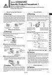
Coil LED Coil (Orange) Diode to prevent reverse current LED (Green) [SOL.b] (+) [SOL.a] (+) COM (.) Switch Switch Coil LED Coil (Orange) Diode to prevent reverse current LED (Green) [SOL.b] (.) [SOL.a] (.) COM (+) ÞNon-locking push type Press in the direction of the arrow. ÞSlide locking type (manual override) Slide the manual override all the way to the ON side in the arrow direction. The manual override is then locked. To unlock the manual override, slide it toward the OFF side in the arrow direction. ÞPush-turn locking slotted type While pressing, turn in the direction of the arrow (90 clockwise). If it is not turned, it can be used in the same way as the nonlocking push type. When the manual override is operated, connected equipment will be actuated. Confirm safety before operating. Warning Manual Override Operation Since the SJ series is a type in which the pilot valve exhaust joins the main valve exhaust inside the valve, use caution, so that the piping from the exhaust port is not restricted. Caution Exhaust Restriction When you operate the D type with a screw driver, turn it gently using a watchmakerfs screw driver. [Torque: under 0.05 NEm] When you lock the manual override of the D type, be sure to push it before turning. [Load: 10 N or less] Turning without pushing can cause damage to the manual override and trouble such as air leakage, etc. Caution Solenoid b Solenoid a Manual override for solenoid b Yellow Manual override for solenoid a Blue Manual override switch When turning OFF the valve using the switch, move it to the position where the valve is locked. If the switch is at an improper position and is energized, equipment connected to the valve could be actuated. Also, if the switch is turned OFF on the valve in the energized state, be careful because any actuators connected to a single solenoid, a dual 3 port valve or a 3 position valve will actuate. Warning Valve with Switch ON OFF ON position OFF ON Switch OFF position OFF ON Electric circuit diagram (with positive common and light/surge voltage suppressor) (with negative common and light/surge voltage suppressor) For manual override operation, move the manual override switch to a position where letters A and B can be seen. [Manual override switch release status (refer to the figure below)] Operation with the manual override switch in a locked status can cause damage to the manual override and air leakage, so be sure to release the manual override switch before use. After manual override operation, lock the manual switch for use (when the manual override of the push-turn locking slotted type is locked, a manual override switch cannot be locked). Warning Manual Override Switch Operation Manual override switch slide direction Manual override switch locked status Manual override switch unlocked status Solenoid b Solenoid a Manual override switch Manual override for solenoid b Yellow Manual override for solenoid a Blue SJ2000: Hole diameter o2.9 SJ3000: Hole diameter o3.4 Enlarged view of manual override part Enlarged view of manual override part 1. Valves with built-in back pressure check valve is to protect the back pressure inside a valve. For this reason, use caution the valves with external pilot specification cannot be pressurized from exhaust port [3/5(E)]. As compared with the types which do not integrate the back pressure check valve, C value of the flow characteristics (sonic conductance) goes down. For details, please contact SMC. 2. Do not switch valves when A or B port is open to the atmosphere, or while the actuators and air operated equipment are in operation. The back pressure prevention seal may be peeled off, which may cause air leakage or malfunctions. Use caution especially when performing a trial operation or maintenance work. Caution Built-in Back Pressure Check Valve Type Normal operation: The valve is switched according to electric signals from the connector on the manifold side. The valve coil is kept in a deenergized state even when there is an electric signal from the connector on the manifold side. 113 Series SJ2000/3000 Specific Product Precautions 1 Be sure to read before handling. Refer to front matter 53 for Safety Instructions and pages 3 to 8 for 3/4/5 Port Solenoid Valve Precautions. SY SJ SY SV SYJ SZ VF VP4 S0700 VQ VQ4 VQ5 VQC VQC4 VQZ SQ VFS VFR VQ7 A