1-p0011-0120-sj2000_en 110 / 111
10秒後にBOOKのページに移動します
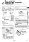
If only connector assembly (for junction common) is ordered, please wire according to the instructions in the diagram below. For details on socket mounting, please refer to "How to Use Plug Connector" on page 117. Caution Wiring Instructions for Connector Assembly (for Junction Common) Wire connection instructions 1. Strip 6.5 to 7.5 mm from the tip of the lead wire. 2. Loosen the terminal screws (slotted head screws) of the power supply terminal connectors, plug the core wire of the lead wire into the square holes of the connector, tighten terminal screws at the proper torque, and fasten them securely. (Gently pull the lead wire and check that it is fastened.) Precautions . To remove the power supply terminal connector, pull it upward as is. When mounting, push it in until it makes a snapping noise. . When connecting wire, be careful because using lead wire that is outside of compatible lead wire ranges, or that are tightened to anything other than the proper torque, creates a risk of defective contact and other problems. Caution How to Wire to PC Wiring System Compliant Power Supply Terminal Connector Assembly Part No. (for Junction Common) Single solenoid SJ3000-46-SC- (for positive common) SJ3000-47-SC- (for negative common) Double solenoid, 3 position type, 4 position type SJ3000-46-DC- (for positive common) SJ3000-47-DC- (for negative common) For single solenoid: For double solenoid For 3 position type : For 4 position type Lead wire length Nil 6 10 15 20 25 30 50 300 mm 600 mm 1000 mm 1500 mm 2000 mm 2500 mm 3000 mm 5000 mm N C (Red) Note) (Black) (Black) (Red) Note) (White) N C How to Order Indicate the part no. of the connector assembly for the manifold and solenoid valve. If the arrangement is complicated, please specify them by means of the manifold specification sheet. Note 1) Applications like connectors not wired to a valve is not possible. Note 2) For the solenoid valve, please designate “No connector (MOZ)” for the connector type. Note 3) Connector assembly with lead wire for place where the signals are transmitted to the common wiring. (Only the valves of first station and/or last station of manifold are compatible to connector with lead wire for common.) The asterisk denotes the symbol for assembly. Prefix it to the part nos. of the solenoid valve, etc. (Example) SS5J3-60-04U............ 1set . SJ3160N-5MOZ-C6... 2set . SJ3260N-5MOZ-C6... 2set . SJ3000-46-S............... 1set (Connector assembly for single solenoid) . SJ3000-46-SC............ 1set (Connector assembly for single solenoid) (for junction common) . SJ3000-46-DC............ 2set (Connector assembly for double solenoid) (for junction common) Double solenoid SJ3260N-5MOZ- Connector assembly (for junction common) SJ3000-46-SC Connector assembly (for junction common) SJ3000-46-DC Common wiring Connector assembly SJ3000-46-S Single solenoid SJ3160N-5MOZ- For junction common Note) In case of negative common, the lead wire changes from red to yellow. SJ3000- 46 -SC- SJ3000- 46 -DCCommon specifications 46 47 For positive common For negative common Lead wire Compatible lead wire range 0.13 to 2.5 mm2 Wire core Insert wire core into the square hole Power supply terminal connector (Detachable) Terminal screws (2 locations) Tightening torque 0.4 to 0.6 N・m PCW type Common wiring Socket Insert the socket into the connector (N) of the neighboring solenoid valve 119 Series SJ2000/3000 Specific Product Precautions 7 Be sure to read before handling. Refer to front matter 53 for Safety Instructions and pages 3 to 8 for 3/4/5 Port Solenoid Valve Precautions. SY SJ SY SV SYJ SZ VF VP4 S0700 VQ VQ4 VQ5 VQC VQC4 VQZ SQ VFS VFR VQ7