1-p0011-0120-sj2000_en 58 / 111
10秒後にBOOKのページに移動します
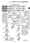
Standard SJ 3 1 60 U C6 With switch SJ 3 Note) Refer to pages 78 and 79 for the dedicated non plug-in individual wiring. SJ 3 1 60 Z C6 1 5 5 5 C M 60 C Z C6 Series SJ2000 SJ3000 2 3 Type of actuation 2 position single solenoid 2 position double solenoid 3 position closed center 3 position exhaust center 3 position pressure center Dual 3 port valve: N.C./N.C. Dual 3 port valve: N.O./N.O. Dual 3 port valve: N.C./N.O. 1 2 3 4 5 A B C None Built-in Nil K Back pressure check valve . Back pressure check valve is not applicable for 3 position solenoid valve. 5 24 VDC Rated voltage Single wiring Double wiring Nil D Single solenoid wiring spec. . There is no need to enter anything for 2 position double, 3 position and 4 position solenoid valves. Select this when the unused numbers to wiring are set. Refer to page 22 for details. A, B port size Straight (Metric size) C2: o2 One-touch fitting C4: o4 One-touch fitting C6: o6 One-touch fitting (SJ3000 only) (Inch size) N1: o1/8" One-touch fitting N3: o5/32" One-touch fitting N7: o1/4" One-touch fitting (SJ3000 only) M3: M3 x 0.5 (SJ2000 only) M5: M5 x 0.8 (SJ3000 only) Elbow fitting assembly (Upward entry) (Metric size) L2: o2 elbow fitting assembly L4: o4 elbow fitting assembly L6: o6 elbow fitting assembly (SJ3000 only) (Inch size) LN1: o1/8" elbow fitting assembly LN3: o5/32" elbow fitting assembly LN7: o1/4" elbow fitting assembly (SJ3000 only) Elbow fitting assembly (Downward entry) (Metric size) B2: o2 elbow fitting assembly B4: o4 elbow fitting assembly B6: o6 elbow fitting assembly (SJ3000 only) (Inch size) BN1: o1/8" elbow fitting assembly BN3: o5/32" elbow fitting assembly BN7: o1/4" elbow fitting assembly (SJ3000 only) Pilot spec. . External pilot spec. is not applicable for 4 position solenoid dual 3 port valves. Internal pilot External pilot Nil R J With switch . Refer to pages 23 through to 30 for the symbol. . Connector entries with the symbol “M” can not use the switch signal from the common wiring on the manifold. For details, refer to “Connector Wiring Diagram” on page 22. . When ordering a connector assembly separately, refer to pages 118 and 119. Connector entry C: Dedicated for centralized wiring M: Individual wiring, With lead wire Length 300 mm MN: Individual wiring, Without lead wire MO: Individual wiring, Without connector With linkage printed circuit board With linkage printed circuit board With linkage printed circuit board Individual wiring [For plug-in mixed mounting]Note) With light/surge voltage suppressor (Non-polar type) With light/surge voltage suppressor (Polar type) Light/surge voltage suppressor U Z . When the types with power saving circuit, with switches, and individual wiring are used, the non-polar type cannot be selected. Standard Coil spec. Nil T . Be sure to select “with power saving circuit” when the solenoid valve will be energized continuously for long period. With power saving circuit (Continuous duty type) Common specifications Manual override Nil: Non-locking push type D: Push-turn locking slotted type F: Slide locking type Protective class class # (Mark: ) . For the non-polar type, there is no need to select a symbol. . When equipped with the standard type switch, select common specifications suitable for the SI unit common specifications. How to Order Solenoid Valves Positive common Negative common Nil N Series SJ2000/3000 EX510 Gateway-type Serial Transmission System Plug-in Connector Type 67 SY SJ SY SV SYJ SZ VF VP4 S0700 VQ VQ4 VQ5 VQC VQC4 VQZ SQ VFS VFR VQ7