1-p0011-0120-sj2000_en 67 / 111
10秒後にBOOKのページに移動します
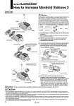
Press the valves and block assemblies to each other for connection. Press the valve lock switch in the cylinder port direction until it does not go any further. Fasten threads a onto the DIN rail. Connect the added valve and SUP/EXH block, and then fasten the DIN rail fixing screws on the end block on the U side. After fixing the connector block assembly, fasten the threads onto the end block assembly while holding it lightly by hand. This is necessary to improve sealing. 4 Loosen threads a, which are fixed onto the DIN rail (two locations). 1 Slide the valve lock switch on each block toward the coil, and then remove the end block assembly and SUP/EXH block assembly. 2 Press the manifold. Press the manifold. Last station Station 1 (“FREE” appears, which indicates the manual switch is locked.) Valve lock switch [Unlocked] a 1. When increasing the number of stations from 10 or below to 11 or above, increase the number of SUP/EXH block assemblies as well. Add the valve to the U side of the last station, and then add the SUP/EXH block assembly to its U side. The SUP/EXH block cannot be added to a position adjacent to the connector block assembly or an intermediate position. 2. Be sure to turn off the power and stop the supply of air before disassembly. Furthermore, since air may remain inside the actuator, piping and manifold, confirm that the air is completely exhausted before performing any work. 3. After assembly and disassembly, air leakage could occur if blocks are not well connected or a thread is not tightly fastened onto the end block assembly. Before supplying air, make sure that no gaps exist in between blocks and that the valve and block are tightly fastened onto the DIN rail. Also, make sure that air is not leaking before use. 4. For the SJ3A6 series manifold with vacuum release valve with restrictor, there is no valve lock switch for connecting, so when mounting, tighten the screws after checking that there are no gaps between valves. To increase a manifold station, a housing holder (refer to the table below) is required in addition to the solenoid valve. D-sub, Connector block assembly for flat ribbon cable, End block assembly M3: 0.6 N・m SJ3000 SJ2000 Series Housing holder part no. Material Note Resin White SJ3000-86-1 SJ2000-86-1 Take out the stored housing for adding the manifold station and assemble it to a newly added housing holder. Insert this housing holder next to the existing housing holder. 3 8 Housing holder Housing Station number imprinting Convex portion for connection q w 8 . Make the number imprinted on the housing matched with the station number. qMount the housing in the arrow direction. wPush in the housing securely using a flat blade screwdriver. How to mount the housing 2. Make the connectors matched with each other. 1. Hook on the rail. 3. Press the manifold in the arrow direction and mount it on the rail. a End block assembly SUP/EXH block assembly Connector block assembly Housing holder (“FREE” cannot be seen.) Valve lock switch [Locked] Connecting hook Valve lock switch Cable Type D side U side D side U side Caution For the manifold with less than the maximum stations, spare housing (for one station) for adding the manifold station is stored in the housing holder of the last station or the SUP/EXH block assembly. To increase a manifold station, follow the steps below to disassemble and reassemble the manifold. [Note: To replace the DIN rail, also loosen the screws (2 locations) on the connector block assembly.] Push this part. Caution Caution Series SJ2000/3000 How to Increase Manifold Stations 2 76