1-p0011-0120-sj2000_en 81 / 111
10秒後にBOOKのページに移動します
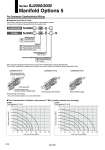
SJ3000 P P P port Regulating port Pressure gauge, top mounting Pressure gauge, side mounting Without pressure gauge 00 01 M1 Option Slotted locking type Manual Nil H Pressure adjustment screw operation Connector type Individual wiring Nil N Wiring spec 00 SJ3000 00 P SJ3A6 SJ2000/3000 N . The valve lock switch available only for series SJ2000/3000. SJ3000(N)-00-P(-H) SJ3000(N)-01-P(-H) SJ3000(N)-M1-P(-H) Pressure gauge, side mounting Without pressure gauge Pressure gauge, top mounting Flow Characteristics (Conditions: Inlet pressure 0.7 MPa 2 position solenoid valve mounting) SJ3000 P port regulation (P→A, B) SJ2000 P port regulation (P→A, B) Note 1) Be sure to apply the pressure from the 1(P) port of the manifold before using the regulator block. Note 2) When ordering with a regulator block installed in the manifold, please order using the manifold specification sheet. 0.8 0.7 0.6 0.5 0.4 0.3 0.2 0.1 Outlet pressure (MPa) Flow rate (L/min (ANR)) 0 20 40 60 80 100 120 140 160 0.8 0.7 0.6 0.5 0.4 0.3 0.2 0.1 Outlet pressure (MPa) Flow rate (L/min (ANR)) 0 20 40 60 80 100 120 140 160 With manual operation of pressure adjustment screw Valve lock switch. No linkage printed circuit board is provided for individual wiring. For Connector Type/Individual Wiring This is used to reduce the pressure supplied from the D side inside the manifold. All valves on the U side are depressurized from the regulator block. Regulator block/How to Order 90 Series SJ2000/3000 Manifold Options 5 A