1-p0011-0120-sj2000_enü@ü@ü@83 / 111
10ĢbīŃé╔BOOKé╠āyü[āWé╔ł┌ō«éĄé▄éĘ
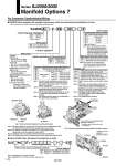
For Connector Type/Individual Wiring Specifications Relieving Non-relieving Nil 2 Symbol Regulator specifications (0.7 MPa specifications) SJ3000 P 1(P) port regulation Lateral Upward A B Handle (Regulator orientation) For connector type For individual wiring Nil N Wiring spec. Without pressure display function Fitting side D side Coil side U side Nil F D C U Pressure switch/ Pressure gauge display orientation Entry is the same as standard products. Without lead wire with connector With lead wire with connector Nil L Digital pressure switch option (external wiring) Analog pressure gauge: The unit of the product nameplate and pressure display is psi. Analog pressure gauge: The unit of the product nameplate and pressure display is MPa. Digital pressure switch: With display unit switching function (Initial valve MPa.) Nil (1) Z (2)(3) ZA (2)(4) Without pressure display function Display unit Analog pressure gauge Digital pressure switch NPN open collector External wiring Internal wiring External wiring Internal wiring PNP open collector Nil A N Q P S Pressure switch/pressure gauge specifications Straight (Metric size) C6: o6 One-touch fitting C8: o8 One-touch fitting (Inch size) N7: o1/4"" One-touch fitting N9: o5/16"" One-touch fitting Elbow fitting (Upward entry) (Metric size) L6: o6 One-touch fitting L8: o8 elbow fitting Elbow fitting (Downward entry) (Metric size) B6: o6 elbow fitting B8: o8 elbow fitting Fitting size A C8 N F . Refer to Figure 1. . Refer to Figure 2. Note) If ügDüh is selected when the connector (D-sub connector, flat ribbon cable, PC wire ring) entry direction is upward, the connector may interfere with the pressure switch wiring depending on the mounting position. So, carefully check this point. Note) When the handle orientation is lateral, the elbow fitting (upward entry) cannot be selected. Note) This option can be selected only when the pressure switch/pressure gauge specifications are ügNüh or ügPüh. Note 1) Digital pressure switch, you will (MPa) a fixed unit. Note 2) According to the New Measurement Law (SI units are used in Japan), these pressure gauges are sold only to the overseas market. Both ügMPaüh and ügpsiüh are written on the unit display of the digital pressure switch. Note 3) The digital pressure switch has the unit conversion function and its initial setting is the ügpsiüh display. Note 4) For digital pressure switches. Note 1) ügInternal wiringüh specifications mean that the wiring is assigned to the centralized wiring on the manifold. (For details, refer to ügElectrical Wiringüh on page 95.) Note 2) For the internal wiring specifications, select an appropriate pressure switch according to the polarity of the valve to be mounted. Note 3) For the serial manifold and non plug-in, ügQüh and ügSüh (internal wiring specifications) cannot be selected. Note 4) The analog pressure gauge is not applicable to the copper-free specifications. (Arrow marks show the display visual observation directions.) Fig.2 Pressure switch/pressure gauge display orientation symbol Fig.1 Handle orientation (Regulator mounting orientation) A: Lateral B: Upward SJ3 60 (T) S Meter-out Meter-in Identification color: Silver Identification color: Black 0 1 Control method 0 Note 1) Applicable only to Series SJ3000. Note 2) Specify S0 or S1 at the end of the valve part no. Fitting side D side Coil side U side Note 1) Be sure to apply the pressure from the 1(P) port of the manifold before using the SUP/EXH block assembly with regulator and pressure switch. Note 2) For details on regulator and electric circuit of the external wiring specifications, see the catalog for Series ARM11. Note 3) Applicable only to the manifolds with the internal pilot specifications. Note 4) This regulator block cannot be combined with the vacuum release valve of Series SJ3A6. Identification color position (Speed controller) Ź SUP/EXH block assembly with regulator and pressure switch (for internal pilot manifold)/How to Order . When mounting on the manifold, specify it in the manifold specification sheet. . This figure shows the pressure switch ügF: Fitting sideüh. Ź Series SJ3000 Valve with Speed Controller/How to Order Regulator handle 3/5(E) port 1(P) port For 4(A) side For 2(B) side 4(A) port 2(B) port 92 Series SJ2000/3000 Manifold Options 7 A