1-p0655-0757-syj3000_en 102 / 104
10秒後にBOOKのページに移動します
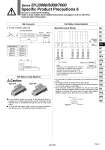
In the manifold valves, the wiring to the individual valves is provided on a printed circuit board, and the connection to the external wires is consolidated through the use of a flat ribbon cable. A single MIL flat ribbon cable connects the entire manifold to your power source. This greatly reduces installation time. Manifold Internal Wiring 123 24 25 26 Flat Ribbon Cable Manifold Flat Ribbon Cable Manifold 22 33.9 14 2. To order connector cable only 3 1 4 Cable length (L) 500 mm 1000 mm 2000 mm 5000 mm No. V100-49-1-2 300 mm V100-49-1-1 V100-49-1-3 V100-49-1-4 V100-49-1-7 Connector dimensions 33.9 o9 L 35 10 M8 Connector Brown: 1 Blue: 3 Black: 4 Type 21P Type 32P Caution Triangle mark indicator position Note) Connector { { Connected on the printed board Station 12 (Max. 12 stations) Common (+) (-) Common (+) (-) A side solenoid (+) (-) B side solenoid (+) (-) { Station 4 A side solenoid (+) (-) B side solenoid (+) (-) { Station 3 A side solenoid (+) (-) B side solenoid (+) (-) { Station 2 A side solenoid (+) (-) B side solenoid (+) (-) { Station 1 A side solenoid (+) (-) B side solenoid (+) (-) Triangle mark Reference figure Note) Terminal no. is not indicated on the connector. The terminal no. indicated in the connection schematic of connector, as shown in the reference, means a correlation of 1, 2, 3・・・・26 from the triangle mark side on the flat ribbon cable of connector. . For more than 10 stations, both poles of the common should be wired. . For single solenoid, connect to the B side solenoid. . The maximum number of stations that can be accommodated is 12. For more stations, contact SMC. . Only non-polar valves are available for the DC flat cable manifold, therefore negative COM or positive COM wiring of the manifold is possible. The valve does not switch with negative COM if a Z type is used. Be sure to use a positive COM. Series SYJ3000/5000/7000 Specific Product Precautions 6 Be sure to read before handling. Refer to front matters 53 for Safety Instructions and pages 3 to 8 for 3/4/5 Port Solenoid Valve Precautions. 26 25 24 23 8 7 6 5 4 3 2 1 Wiring unit Station B side solenoid A side solenoid 755 SY SJ SY SV SYJ SZ VF VP4 S0700 VQ VQ4 VQ5 VQC VQC4 VQZ SQ VFS VFR VQ7 A