1-p0655-0757-syj3000_en 67 / 104
10秒後にBOOKのページに移動します
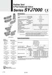
(R1)5 (A)4 2(B) 1 (P) 3(R2) (A)4 2(B) (R1)5 1 (P) 3(R2) (A)4 2(B) (R1)5 1 (P) 3(R2) (A)4 2(B) (R1)5 1 (P) 3(R2) (A)4 2(B) (R1)5 1 (P) 3(R2) (B)2 4(A) 1 (P) (R2)3 5(R1) (B)2 4(A) (R2)3 1 5(R1) (P) (B)2 4(A) (R2)3 1 5(R1) (P) (B)2 4(A) (R2)3 1 5(R1) (P) (B)2 4(A) (R2)3 1 5(R1) (P) Symbol 2 position single Body ported 2 position single solenoid Base mounted Body ported Base mounted [Option] Rubber Seal 5 Port Solenoid Valve Series SYJ7000 2 position double 3 position closed center 3 position exhaust center 3 position pressure center 2 position double solenoid 3 position closed center 3 position exhaust center 3 position pressure center Made to Order (For details, refer to pages 748 and 749.) Solenoid Specifications Electrical entry Coil rated voltage (V) Allowable voltage fluctuation Power consumption (W) Apparent power (VA). Surge voltage suppressor Indicator light 100, 110, 200, 220 ±10% of rated voltage . 0.35 {With light: 0.4 (DIN terminal with light: 0.45)} Diode (DIN terminal, Varistor when non-polar types) LED (Neon light when AC with DIN terminal) 0.1 (With light only) . [Starting 0.4, Holding 0.1] Grommet (G), (H) L plug connector (L) M plug connector (M) DIN terminal (D), (Y) M8 connector (W) AC DC AC 50/60 Hz DC 100 V 110 V [115 V] 200 V 220 V [230 V] Standard With power saving circuit G, H, L, M, W 24, 12, 6, 5, 3 D, Y 24, 12 0.78 (With light: 0.81) 0.86 (With light: 0.89) [0.94 (With light: 0.97)] 1.18 (With light: 1.22) 1.30 (With light: 1.34) [1.42 (With light: 1.46)] 0.78 (With light: 0.87) 0.86 (With light: 0.97) [0.94 (With light: 1.07)] 1.15 (With light: 1.30) 1.27 (With light: 1.46) [1.39 (With light: 1.60)] Specifications Fluid Operating pressure range (MPa) Ambient and fluid temperature (°C) Response time (ms) (at 0.5 MPa) Max. operating frequency (Hz) Manual override (Manual operation) Pilot exhaust method Lubrication Mounting orientation Impact/Vibration resistance (m/s2) Enclosure 2 position single 2 position double 3 position 2 position single, double 3 position 2 position single, double 3 position Note 1) Note 2) . Based on IEC60529 Note 1) Based on dynamic performance test, JIS B 8375-1981. (Coil temperature: 20°C, at rated voltage, without surge suppressor) Note 2) Impact resistance: No malfunction occurred when it is tested in the axial direction and at the right angles to the main valve and armature in both energized and de-energized states every once for each condition. (Value in the initial state) Vibration resistance: No malfunction occurred in one sweep test between 45 and 2000 Hz. Test was performed at both energized and de-energized states in the axial direction and at the right angles to the main valve and armature. (Value in the initial state) Air 0.15 to 0.7 0.1 to 0.7 0.15 to 0.7 .10 to 50 (No freezing) 30 or less 60 or less 5 3 Non-locking push type, Push-turn locking slotted type, Push-turn locking lever type Individual exhaust for the pilot valve, Common exhaust for the pilot and main valve Not required Unrestricted 150/30 Dust proof (. M8 connector conforms to IP65.) . In common between 110 VAC and 115 VAC, and between 220 VAC and 230 VAC. . For 115 VAC and 230 VAC, the allowable voltage is .15% to +5% of rated voltage. . For details refer to page 752. B 720