1-p0655-0757-syj3000_enü@ü@ü@68 / 104
10ĢbīŃé╔BOOKé╠āyü[āWé╔ł┌ō«éĄé▄éĘ
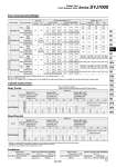
Flow Characteristics/Weight SYJ7120-01 Body ported Tubing bore x Length Speed controller Silencer Series CJ2 Series CM2 o6 x 1 m AS3302F-06 o12 x 1 m AS4002F-12 AN20-02 AS2302F-06 AN110-01 Series MB/CA2 SYJ7140-02 Base mounted Tubing bore x Length Speed controller Silencer Series CJ2 Series CM2 AN110-01 Series MB/CA2 AN20-02 AN3301F-06 AS1302F-06 o6 x 1 m AS3002F-06 Series SYJ7120-01 Average speed (mm/s) Bore size Series CJ2 Pressure 0.5 MPa Load rate: 50% Stroke 60 mm Series CM2 Pressure 0.5 MPa Load rate: 50% Stroke 300 mm Series MB, CA2 Pressure 0.5 MPa Load rate: 50% Stroke 500 mm o6 o10 o16 o20 o25 o32 o40 o40 o50 o63 o80 o100 Use as a guide for selection. Body Ported Please confirm the actual conditions with SMC Sizing Program. Perpendicular, upward actuation Horizontal actuation Series SYJ7140-02 Average speed (mm/s) Bore size Series CJ2 Pressure 0.5 MPa Load rate: 50% Stroke 60 mm Series CM2 Pressure 0.5 MPa Load rate: 50% Stroke 300 mm Series MB, CA2 Pressure 0.5 MPa Load rate: 50% Stroke 500 mm o6 o10 o16 o20 o25 o32 o40 o40 o50 o63 o80 o100 . Cylinder is in extending. Speed controller is meter-out, which is directly connected with cylinder and its needle is fully opened. . Average speed of cylinder is obtained by dividing the full stroke time by the stroke. . Load factor: ( (Load weight x 9.8) /Theoretical force) x 100% Perpendicular, upward actuation Horizontal actuation Base Mounted Conditions C [dm3/(süEbar)] 2.2 1.8 1.2 3.0 [0.83] 1.6 1.4 1.1 1.8 [0.78] 2.0 1.7 1.2 1.9 [0.86] 2.3 1.9 1.2 3.3 [0.85] 2.3 1.9 1.3 3.6 [0.83] b 0.36 0.37 0.50 0.37 [0.50] 0.33 0.27 0.37 0.36 [0.40] 0.39 0.35 0.38 0.57 [0.46] 0.45 0.36 0.48 0.43 [0.54] 0.41 0.46 0.45 0.23 [0.55] Cv 0.58 0.45 0.34 0.78 [0.25] 0.4 0.35 0.27 0.45 [0.22] 0.52 0.42 0.33 0.59 [0.25] 0.57 0.48 0.35 0.78 [0.25] 0.61 0.50 0.35 0.84 [0.25] Weight (g) Note 2, 3) Grommet 85 98 108 96 109 119 96 109 119 165 (85) 178 (98) 188 (108) 165 (85) 178 (98) 188 (108) DIN terminal 107 142 152 98 153 163 98 153 163 187 (107) 222 (142) 232 (152) 187 (107) 222 (142) 232 (152) M8 connector 90 108 118 101 119 129 101 119 129 170 (90) 188 (108) 198 (118) 170 (90) 188 (108) 198 (118) L/M plug connector 86 100 110 97 111 121 97 111 121 166 (86) 180 (100) 190 (110) 166 (86) 180 (100) 190 (110) Port size Valve model Type of actuation SYJ7Ł20-Ł-01 SYJ7Ł20-Ł-C6 SYJ7Ł20-Ł-C8 SYJ7Ł40-Ł-01 SYJ7Ł40-Ł-02 C [dm3/(süEbar)] 2.4 2.0 3.0 [1.3] 1.8 2.2 1.9 2.5 [1.3] 1.6 2.3 2.0 2.6 [1.3] 1.7 2.8 2.1 3.4 [1.3] 2.1 2.9 2.2 3.7 [1.4] 2.1 b 0.34 0.35 0.35[0.52] 0.37 0.32 0.33 0.32[0.54] 0.30 0.34 0.29 0.35[0.49] 0.39 0.37 0.46 0.36[0.57] 0.45 0.35 0.44 0.27[0.56] 0.47 Cv 0.63 0.49 0.73 [0.39] 0.45 0.53 0.49 0.61 [0.38] 0.39 0.61 0.49 0.67 [0.38] 0.42 0.71 0.57 0.86 [0.41] 0.56 0.74 0.60 0.87 [0.43] 0.58 Flow characteristics Note 1) 4,2 1ā»4/2 (Pā»A/B) (A,B) 1,5,3 (P,EA,EB) 4/2ā»5/3 (A/Bā»EA/EB) Base mounted Body ported 1/8 1/8 1/8 1/8 1/8 1/8 C6 (One-touch fitting for o6) C8 (One-touch fitting for o8) 2 position 3 position 2 position 3 position 2 position 3 position 2 position 3 position 1/4 1/4 2 position 3 position Cylinder Speed Chart Note 1) [ ]: denotes the normal position. Exhaust center: 4/2 ü© 5/3, Pressure center: 1 ü© 4/2 Note 2) ( ): Without sub-plate. Note 3) For DC voltages. For AC voltages add 3 g to the weight of the single solenoid and 6 g to the weight of the double solenoid and 3 position types. 800 700 600 500 400 300 200 100 0 800 700 600 500 400 300 200 100 0 Rubber Seal Series SYJ7000 5 Port Solenoid Valve Single Double Closed center Exhaust center Pressure center Single Double Closed center Exhaust center Pressure center Single Double Closed center Exhaust center Pressure center Single Double Closed center Exhaust center Pressure center Single Double Closed center Exhaust center Pressure center 721 SY SJ SY SV SYJ SZ VF VP4 S0700 VQ VQ4 VQ5 VQC VQC4 VQZ SQ VFS VFR VQ7