1-p0655-0757-syj3000_en 82 / 104
10秒後にBOOKのページに移動します
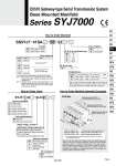
Refer to page 2124 and the Operation Manual for the details of EX510 Gateway-type Serial Transmission System. Please download the Operation Manual via our website, http://www.smcworld.com 01 A, B port size 1/8 SS5YJ7 41SA 01 Nil F N T P, R, A, B port thread type Rc G NPT NPTF SYJ7 43 5LO 1 2 3 4 5 2 position single 2 position double 3 position closed center 3 position exhaust center 3 position pressure center Type of actuation Rated voltage: 24 VDC Light/Surge voltage suppressor Manual override Add the valve and option part numbers under the manifold base part number. In the case of complex arrangement, specify them on the manifold specification sheet. The connector assembly lead wire length used for EX510 manifold varies depending on the number of stations. Therefore, solenoid valves (including a blanking plate) and connector assembly are assembled when shipped as a standard specification. Please specify the mounting solenoid valve when ordering. SS5YJ7-41SA-05 (-Q) ・・・・・ 1 set (Type 41SA 5-station manifold part no.) . SYJ7143-5LOU-01 (-Q) ・・・ 3 sets ( 5-station manifold part no.) . SYJ7243-5LOU-01 (-Q) ・・・ 2 sets (Double solenoid part no.) 03 1 Z B B B B B 8 6 4 2 0 A A A A A Stations・・・・・・・3 2 1 Double solenoid (24 VDC) SYJ7243-5LOU-01(-Q) (2 sets) Single solenoid (24 VDC) SYJ7143-5LOU-01(-Q) (3 sets) Manifold base (5 stations) SS5YJ7-41SA-01(-Q) Series SYJ7000 [Option] EX510 Gateway-type Serial Transmission System Base Mounted Manifold How to Order Manifold Nil N NPN output (+ COM.) PNP output (. COM.) SI unit Valve stations ・ The number of the blanking plate assembly is also included. Note 1) Double wiring: Use of a single solenoid will result in an unused control signal. If this is not desired, order with a specified layout. Note 2) Specified layout: Indicate wiring specifications on the manifold specification sheet. (Note that double and 3 position valves cannot be used where single solenoid wiring has been specified.) Symbol 03 08 03 16 Station 3 stations 8 stations 3 stations 16 stations Note Double wiring Note 1) Specified layout Note 2) (Up to 16 solenoids) ・・・ ・・・ ・・・ ・・・ Symbol Nil N SI unit part no. SI unit specifications NPN output (+ COM.) PNP output (. COM.) SI unit part no. EX510-S001 EX510-S101 Page P.2143 Nil Q . CE-compliant CE-compliant How to Order Valve Z U With light/surge voltage suppressor Without light/surge voltage suppressor (non-polar type) Nil D E Non-locking push type Push-turn locking slotted type Push-turn locking lever type Nil Q . CE-compliant CE-compliant Example How to Order Manifold Assembly (Example) The asterisk denotes the symbol for assembly. Prefix it to the part nos. of the solenoid valve, etc. Coil specifications Nil T Standard With power saving circuit . Power saving circuit is only available in the “Z” type. 735 SY SJ SY SV SYJ SZ VF VP4 S0700 VQ VQ4 VQ5 VQC VQC4 VQZ SQ VFS VFR VQ7 A