1-p0803-0861-vf1000_en 22 / 62
10秒後にBOOKのページに移動します
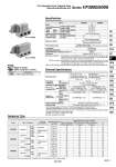
Series VF5000 Series VF3000 Specifications Response Time Note) Based on dynamic performance test, JIS B 8375-1981. (Coil temperature: 20°C, at rated voltage) VF1000 VF3000 VF5000 2-position 2-position 2-position 2-position 2-position 3-position 3-position 3-position 3-position Response time (ms) (at 0.5 MPa) Without light/surge voltage suppressor With light/surge voltage suppressor S, Z type Type of actuation Pressure specifications Single Double Single Double Single Double Single Double Single Double Single Double Standard High-pressure type Standard High-pressure type Standard High-pressure type 0.15 to 0.7 0.1 to 0.7 0.15 to 1.0 0.1 to 1.0 0.15 to 0.7 0.1 to 0.7 0.15 to 0.7 0.15 to 1.0 0.1 to 1.0 0.15 to 1.0 0.15 to 0.7 0.1 to 0.7 0.15 to 0.7 0.15 to 1.0 0.1 to 1.0 0.15 to 1.0 20 12 23 15 20 12 30 23 15 33 30 15 50 33 18 53 45 12 48 15 45 12 55 48 15 58 55 15 75 58 18 78 R, U type 23 12 26 15 23 12 33 26 15 36 33 15 53 36 18 56 AC 45 12 48 15 45 12 55 48 15 58 55 15 75 58 18 78 Operating pressure range (MPa) Series Air 0.15 to 0.7 0.1 to 0.7 0.15 to 1.0 0.1 to 1.0 .10 to 50 (No freezing) 10 3 Individual exhaust, Main/ Pilot valve common exhaust Pilot valve base exhaust 5 3 Non-locking push type Push-turn locking slotted type Push-turn locking lever type Not required Unrestricted 300/50 Dustproof (IP65. for D, Y, T) 2-position single/3-position 2-position double 2-position single/3-position 2-position double Standard Highpressure type 2-position single/double 3-position Model VF3000 VF5000 Series VF3000/5000 Pilot Operated 5 Port Solenoid Valve Base Mounted/Single Unit Made to Order Made to Order (Refer to page 821 for details.) X600 TRIAC output specification Symbol Specification Note) Impact resistance: Vibration resistance: No malfunction occurred in a one-sweep test between 45 and 2000 Hz. Test was performed at both energized and de-energized states in the axial direction and at the right angles to the main valve and armature. (Values at the initial period) . Based on IEC 60529. When using IP65, select the main/pilot valve common exhaust type or pilot valve base exhaust type. No malfunction occurred when it is tested in the axial direction and at the right angles to the main valve and armature in both energized and de-energized states every once for each condition. (Values at the initial period) Fluid Operating pressure range (MPa) Ambient and fluid temperature (°C) Max. operating frequency (Hz) Manual override Pilot exhaust type Lubrication Mounting orientation Impact/Vibration resistance (m/s2) Note) Enclosure Solenoid Specifications . It is in common between 110 VAC and 115 VAC, and between 220 VAC and 230 VAC. . Allowable voltage fluctuation is .15% to +5% of the rated voltage for 115 VAC or 230 VAC. . Since voltage drops due to the internal circuit in S, Z, T types (with power saving circuit), the allowable voltage fluctuation should be within the following range. 24 VDC: .7% to +10% 12 VDC: .4% to +10% Note) Refer to page 858 for details. 24, 12 24, 100, 110, 200, 220, 240 ±10% of rated voltage. Diode (Non-polar type: Varistor) LED (Neon light is used for AC mode of D, Y, T.) Grommet (G), (H) L-type plug connector (L) M-type plug connector (M) DIN terminal (D) DIN (EN175301-803) terminal (Y) Conduit terminal (T) G, H, L, M 1.5 (With light: 1.55) 1.5 (With light: 1.55) 1.55 (With light: 1.65) D, Y, T 1.5 (With light: 1.75) 1.5 (With light: 1.75) 1.55 (With light: 1.7) 0.55 Note) (With light only) [Starting 1.55 Holding 0.55] 0.75 Note) (With light only) [Starting 1.75 Holding 0.75] Electrical entry DC AC (50/60 Hz) Standard 24 V 100 V 110 V [115 V] 200 V 220 V [230 V] 240 V DC Coil rated voltage (V) Allowable voltage fluctuation Power consumption (W) Apparent power (VA). Surge voltage suppressor Indicator light With power saving circuit AC 823 SY SJ SY SV SYJ SZ VF VP4 S0700 VQ VQ4 VQ5 VQC VQC4 VQZ SQ VFS VFR VQ7 A