1-p0803-0861-vf1000_en 48 / 62
10秒後にBOOKのページに移動します
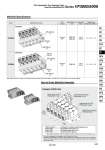
D side Manifold Specifications Example (VV5F3-40) How to Order Manifold Assembly Closed center (24 VDC) VF3340-5GZ1 (1 set) Double solenoid (24 VDC) VF3240-5GZ1 (1 set) Single solenoid (24 VDC) VF3140-5GZ1 (3 sets) Manifold base (5 stations) VV5F3-40-052-02 U side 1 3 2 Stations . The valve arrangement is numbered as the 1st station from D side. . Under the manifold base part number, state the valves to be mounted in order from the 1st station as shown in the figure above. If the arrangement becomes complicated, specify on the manifold specification sheet. The asterisk denotes the symbol for assembly. Prefix it to the part nos. of the solenoid valve, etc. VV5F3-40-052-02 ・・・・・・・・・・・・・ 1 set (Type 40, 5-station manifold base part no.) . VF3140-5GZ1 ・・・・・・・・・・・・・・・・・・ 3 sets (Single solenoid part no.) . VF3240-5GZ1 ・・・・・・・・・・・・・・・・・・ 1 set (Double solenoid part no.) . VF3340-5GZ1 ・・・・・・・・・・・・・・・・・・ 1 set (Closed center part no.) Applicable stations Applicable valve model EXH port type Series Manifold base model Common EXH 2 to 20 stations W = 110n + 116 VF3𡱖40 VF3𡱖43 VV5F3-40 Manifold base Weight: W [g] Stations: n VF3000 Common EXH 2 to 10 VF5𡱖44 stations W = 161n + 128 VV5F5-40 VF5000 Note) Supply pressure to 1(P) ports and exhaust pressure from R ports on both sides for 10 stations or more (5 stations or more for the VF5000). Series VF3000/5000 Pilot Operated 5 Port Solenoid Valve Base Mounted/Manifold 1(P) port 1/4 5(R), 3(R) port 1/4 4(A), 2(B) port 1/4 1(P) port 3/8 5(R), 3(R) port 3/8 4(A), 2(B) port 1/4 PE port M5 x 0.8 849 SY SJ SY SV SYJ SZ VF VP4 S0700 VQ VQ4 VQ5 VQC VQC4 VQZ SQ VFS VFR VQ7